There are 2 methods for updating the BIOS using Instant Flash.
Method 1:
- Save the BIOS files on a device such as USB disk (FAT32 format), hard disk (FAT32 format) and floppy drive.
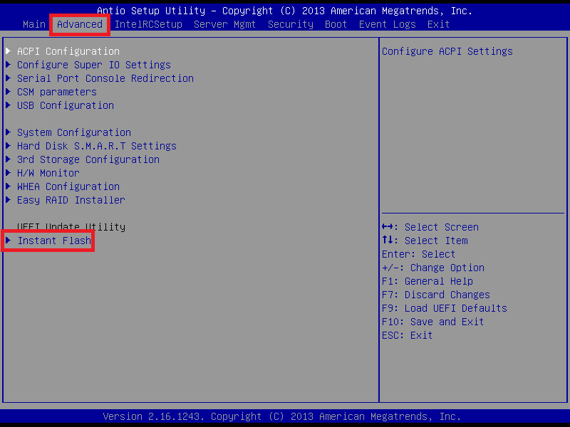
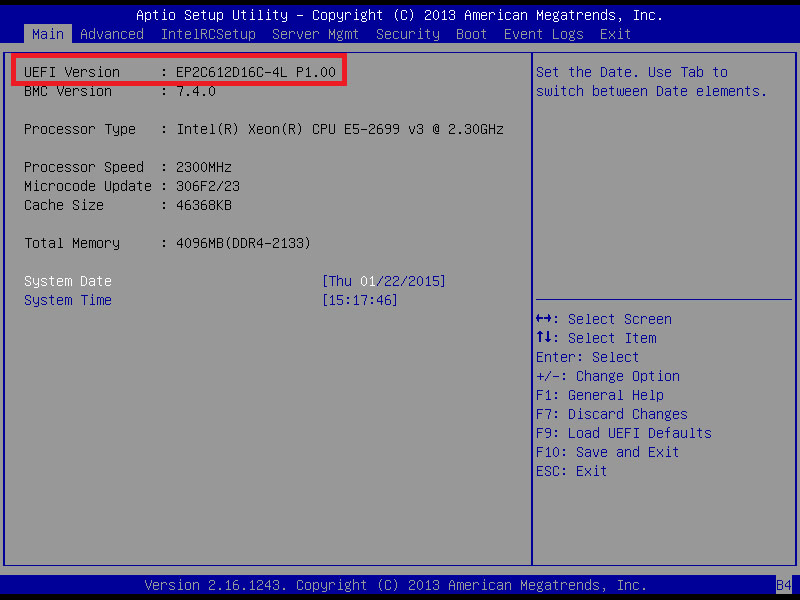
- Press [F2] during POST to get into BIOS setup menu.
- Select the Instant flash under [Advanced] menu to execute it.
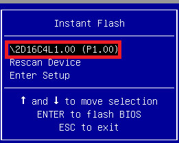
- ASRock Instant Flash will automatically detect all devices and only list those BIOS versions which are suitable for your motherboard, and select the suitable BIOS version and flash.
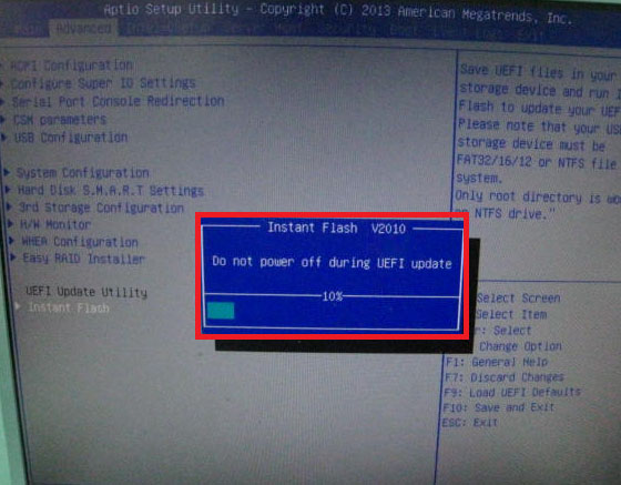
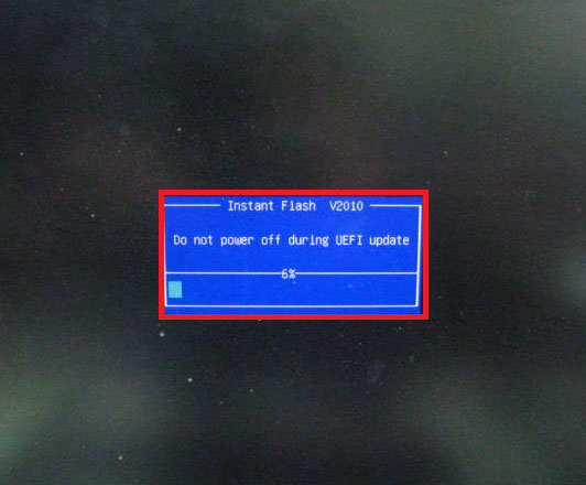
- Please DO NOT power off during BIOS update.
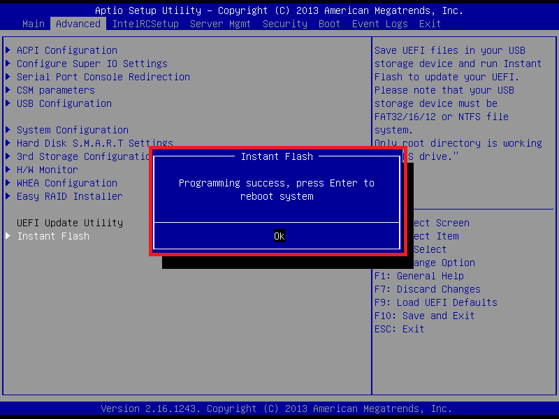
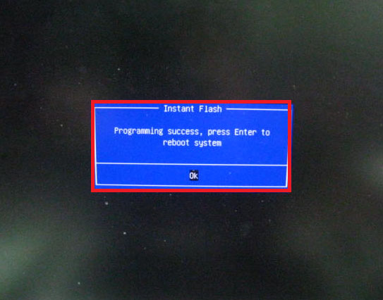
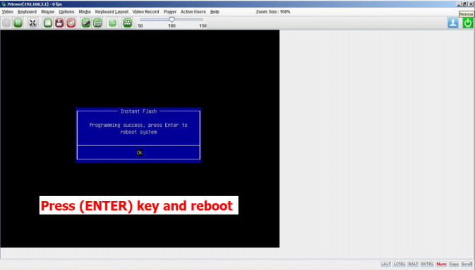
- After update success, it will pop up below massage. Please press Enter to reboot system.
- After system restart, press [F2] or [Del] to enter the BIOS setup utility during boot up to check BIOS version.
- In Exit menu, please select "Load Default Settings" and press [Enter] to continue.
- Select "Exit Saving Changes" and press [Enter] to exit the BIOS setup utility.
Method 2:
- Save the BIOS files on a device such as USB disk (FAT32 format), hard disk (FAT32 format) and floppy drive.
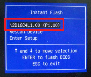
- Press [F6] when you see this (or similar) page.

- Select the suitable BIOS version and flash.
- Please DO NOT power off during BIOS update.
- After update success, it will pop up below massage. Please press Enter to reboot system.
- After system restart, press [F2] or [Del] to enter the BIOS setup utility during boot up to check BIOS version.
- In Exit menu, please select "Load Default Settings" and press [Enter] to continue.
- Select "Exit Saving Changes" and press [Enter] to exit the BIOS setup utility.
- Now, system is booting up with new BIOS.
If you encounter problems while updating the new BIOS, DO NOT turn off your system since this corrupt BIOS might cause your system failed to boot up. Just repeat the process, and if the problem still persists, update the original BIOS file. If the Flash Memory Writer utility was not able to successfully update a complete BIOS file, your system may not be able to boot up. If this happens, your system will need service.
This utility works in Microsoft® Windows 7 (32 / 64 bit), Windows 8 (32 / 64 bit), Windows 8.1 (32 / 64 bit), Server 2008 R2 SP1 (64 bit), Server 2012 (64 bit),Server 2012 R2 (64 bit).
- Download the BIOS package (WinZip format with .zip file extension). And close all programs.
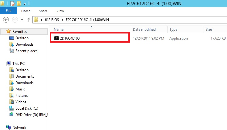
- Unzip and save all files to the same directory of any storage location accessible by the host system.
- Click BIOSfilename.exe
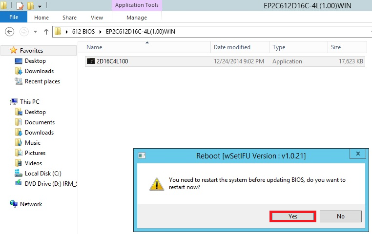
- It shows a dialog icon to remind you need to restart the system before updating BIOS. Click "Yes".
- System will auto restart, and update BIOS. Please DO NOT power off during BIOS update.

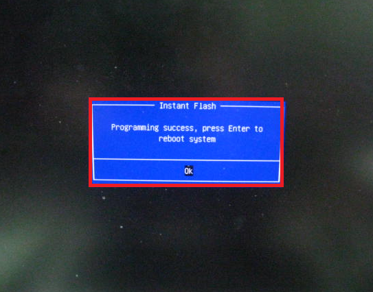
- After update success, it will pop up below massage. Please press Enter to reboot system.
- After system restart, press [F2] or [Del] to enter the BIOS setup utility during boot up to check BIOS version.

- In Exit menu, please select "Load Default Settings" and press [Enter] to continue.
- Select "Exit Saving Changes" and press [Enter] to exit the BIOS setup utility.
- Now, system is booting up with new BIOS.
If you encounter problems while updating the new BIOS, DO NOT turn off your system since this corrupt BIOS might cause your system failed to boot up. Just repeat the process, and if the problem still persists, update the original BIOS file. If the Flash Memory Writer utility was not able to successfully update a complete BIOS file, your system may not be able to boot up. If this happens, your system will need service
To update the BMC firmware via IPMI, please follow the steps below.
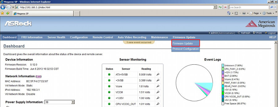
- Enter the management system and click the Firmware Update from the top menu bar.*Note: please make sure your browser is IE v11.0.9600.17239, FireFox v31.0, Chrome v37.0.2062.120 or above version.
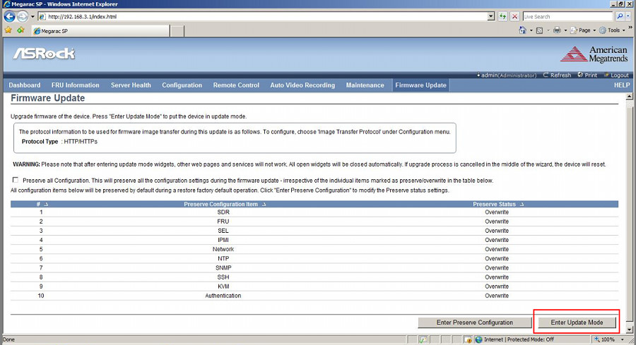
- Click Enter Update Mode > OK.
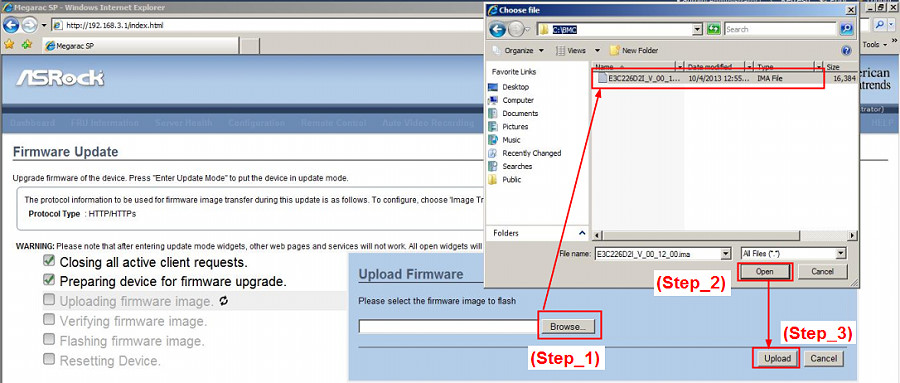
- Click Browse… to select the BMC firmware file from the directory. Click Open > Upload.
- Click Proceed > OK to start.
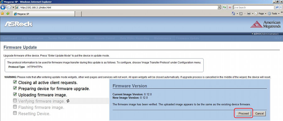
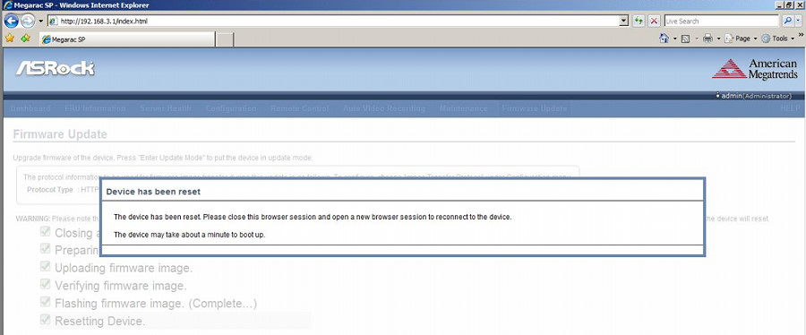
- When you see the screen below, firmware upgrade is completed.
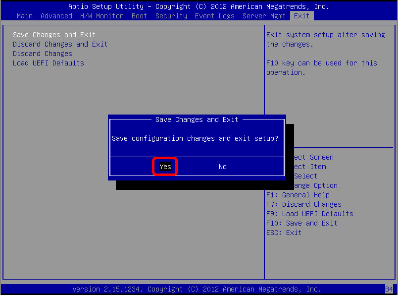
- Go back to your server and, in the BIOS screen, press [F10] and Yes to save the configuration changes and reboot the server.
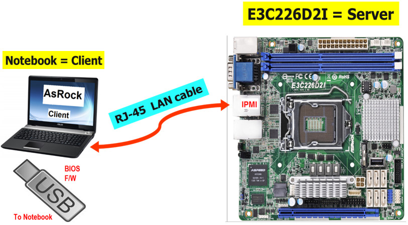
- Make sure you have connected a LAN cable from the laptop (client) to the dedicated IPMI LAN port on the Server. Prepare an USB device with the BIOS firmware installed.
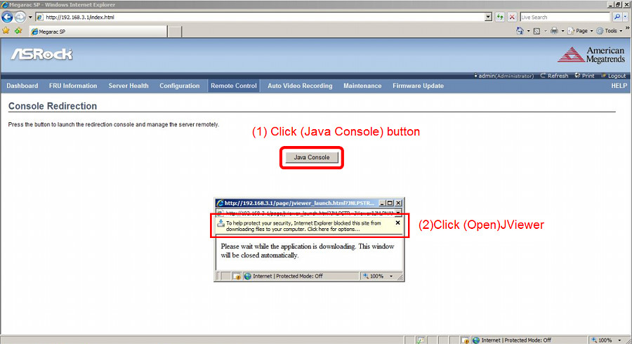
- Enter the management system from your laptop (client). Go to Remote Control > Console Redirection.

- Click Java Console > Open to open the JViewer.
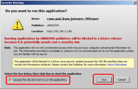
- Select “I accept the risk and want to run this application.” and click Run to launch the JViewer.
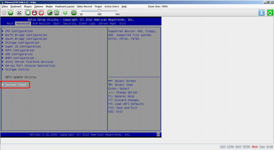
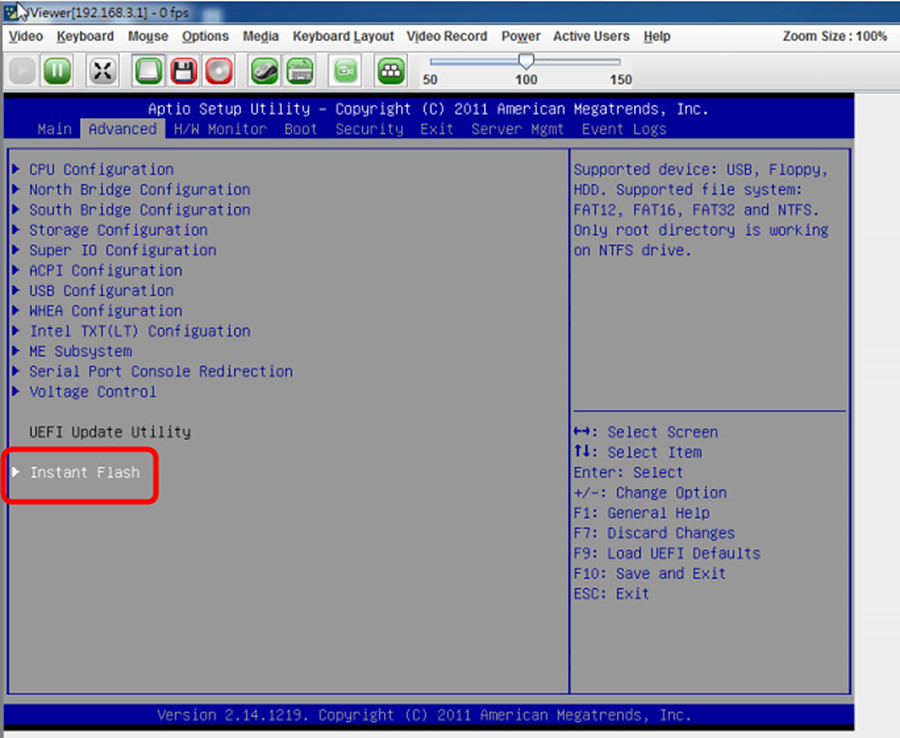
- In the BIOS screen, go to Advanced > Instant Flash.
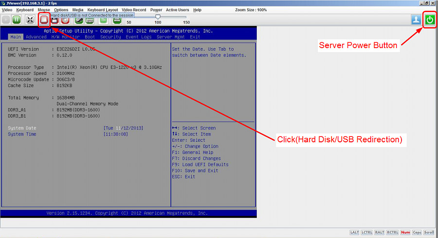
- Insert the USB device with the BIOS firmware installed into your laptop (client).

- Click Hard Disk/USB Redirection.
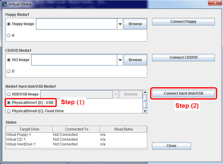
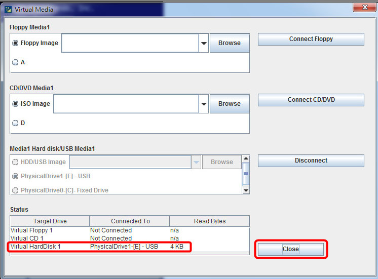
- Select the inserted USB and click Connect Hard disk/USB.
- Confirm the inserted USB device is found and click Close to exit.
- In the BIOS, go to Advanced > Instant Flash and press the [Enter] key on the keyboard to select.
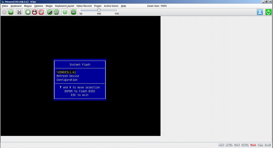
- Choose the desired BIOS firmware and press [Enter].
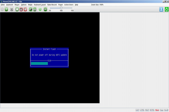
- The BIOS updating begins.
- After upgrade, press [Enter] key to reboot the server and confirm the BIOS and BMC versions.
 The format of our documents are in PDF files. If you have not installed Adobe Acrobat Reader, please get it from Adobe.
IPMI Configuration User Guide (PDF)
If the error icon is visible, then this will prevent you from have any audio functionality on your PC or virtual machine. The first image below highlights the error icon.
- Windows Server 2012 or 2012R2 : Click Start > Administrative Tools > Services
- Locate the Windows Audio service as shown below:
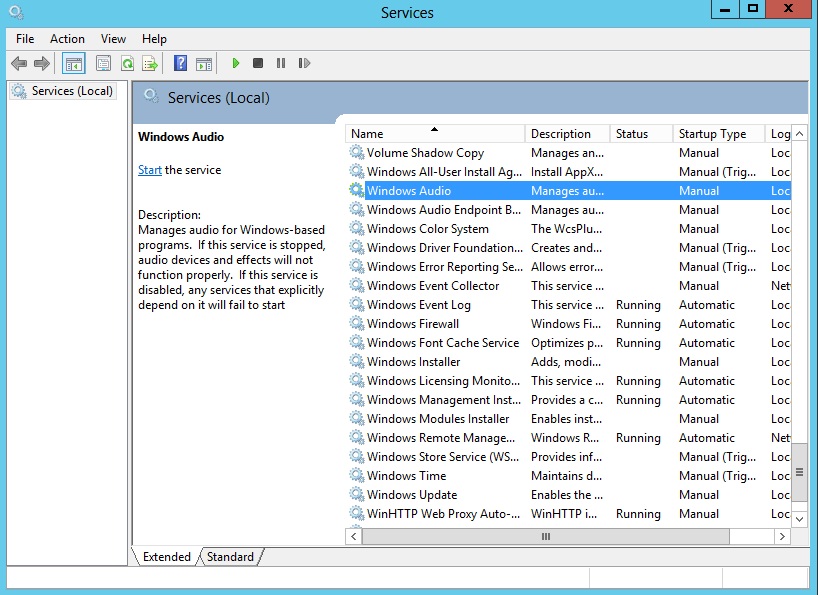
- Right-click on the Windows Audio and select Properties
- Set the Startup type to Automatic
- Click Start. Wait for the start process to complete.
- Click OK to complete the process.
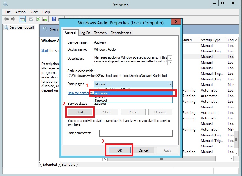
Now your Windows Audio service should be running and the error icon has been removed as shown below.
- Equipment preparations:
RJ45 Ethernet cable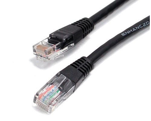
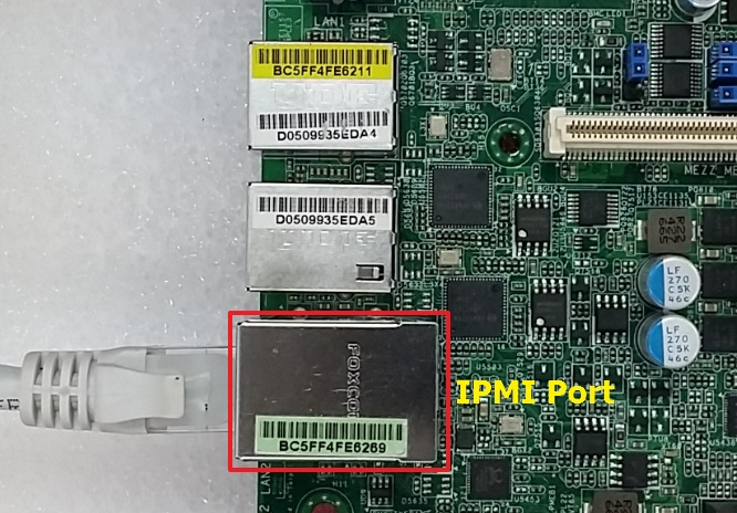
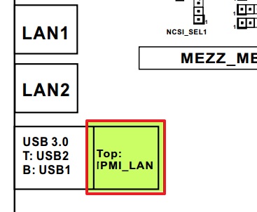
- Make sure RJ45 port plug into IPMI_LAN port on the server side board, the RJ45 port plug into general LAN port on client side.
- Please follow the BIOS setting for the server side: Advanced→Serial Port Console Redirection→
SOL
- Console Redirection: [Enable]
- Console Redirection Settings:
Bits per second: [115200]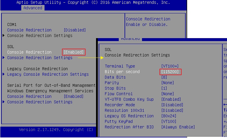
- Legacy Console Redirection
- Legacy Serial Redirec: [SOL]
Legacy Serial Redirec: [SOL]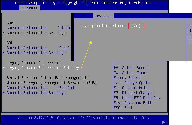
- Windows EMS
- Console Redirection: [Enable]
- Console Redirection Settings:
Out-of-Band Mgmt Port: [SOL]
Bits per second: [115200]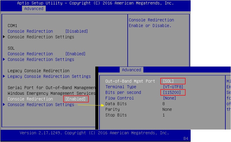
- Megarac SP setting (client side): Remote Control→Java SOL
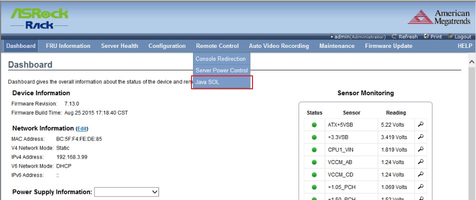
Click the [Java SOL]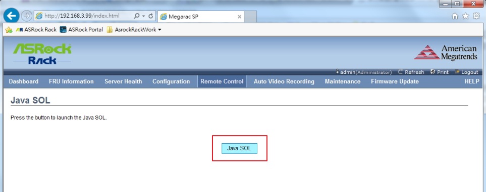
NOTE: A compatible JRE must be installed in the system prior to the launch of the JNLP file. - Please follow the Java SOL setting, and click [Connect].
BMC IP: {Station IP address}
Username: {Megarac SP login ID} ** “admin” in default
Password: {Megarac SP login password} ** “admin” in default
Volatile-Bit-Rate: [115.2K]
Non-Volatile-Bit-Rate: [115.2K]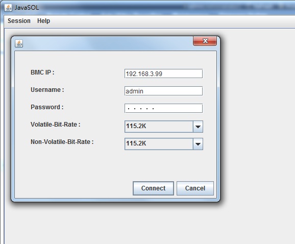
- eboot server system and SOL has start working.
SOL to BIOS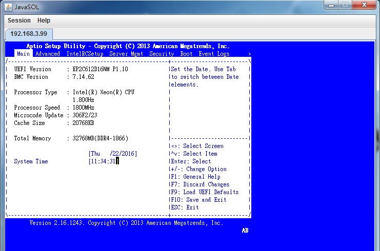
SOL to PXE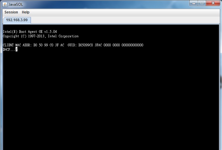
SOL to UEFI PXE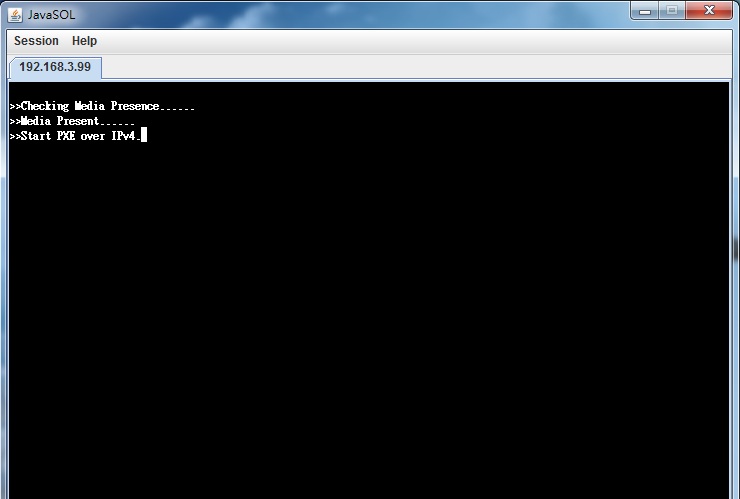
SOL to OS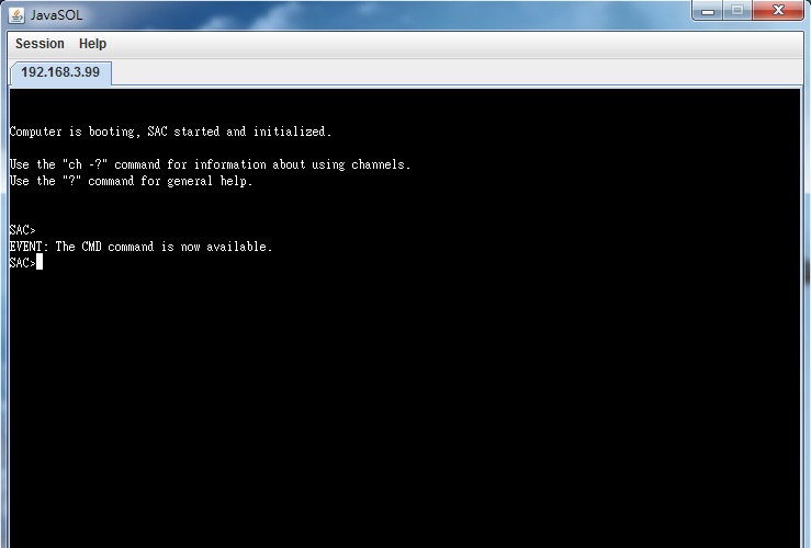
- 1. Equipment preparations:
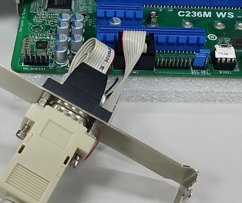
RS232 COM port
RS232 COM port cable
Putty terminal emulator application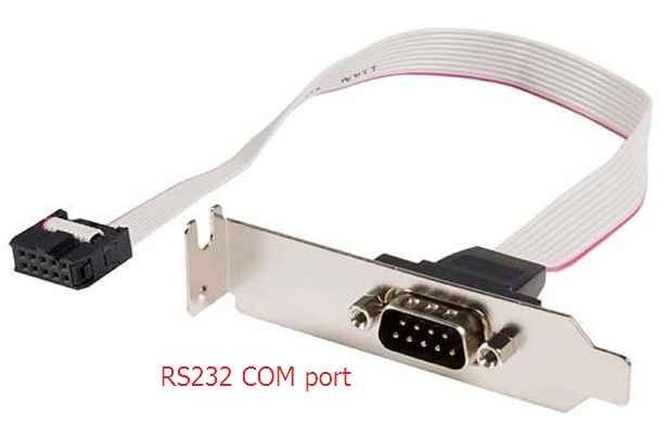
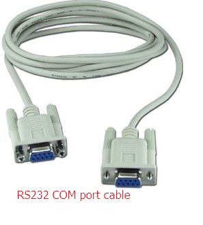

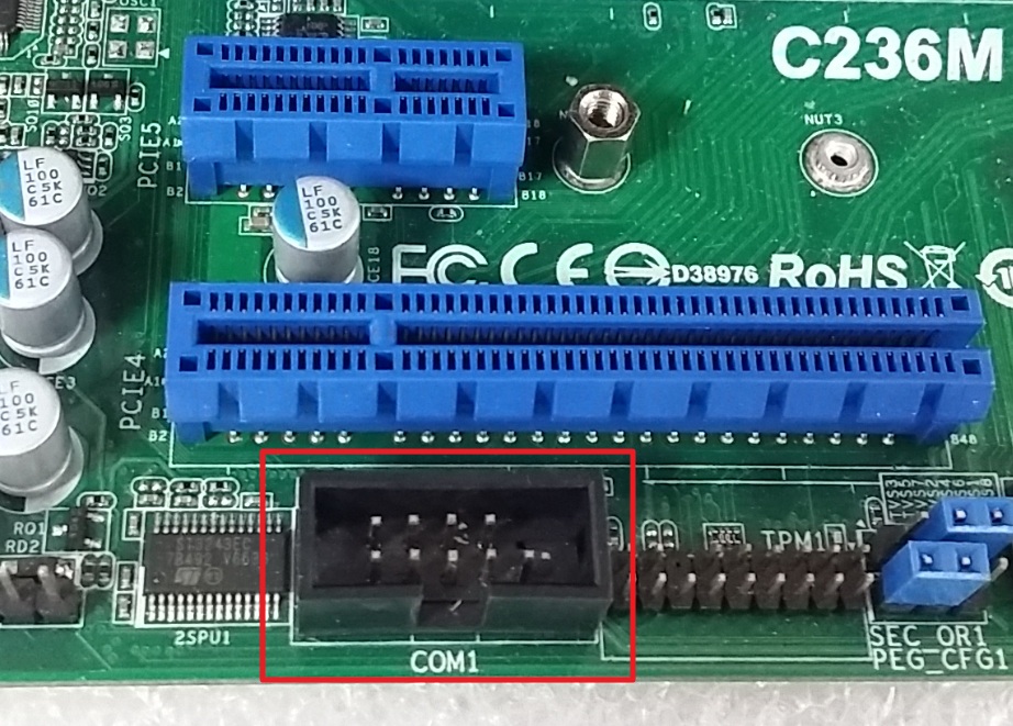
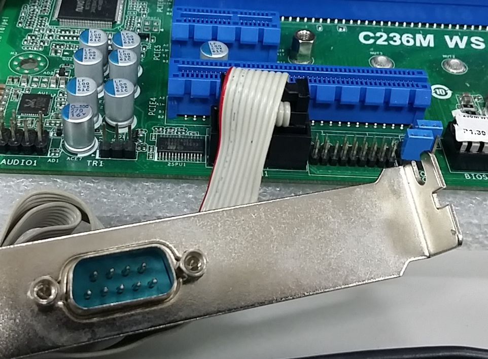
- Make sure RS232 COM port plug into COM1 on the board, and the RS232 COM port cable are connect in both server & client side’ RS232 COM port.
- Execute the Putty terminal emulator application

- BIOS setting: Advanced→Serial Port Console Redirection→COM1 & EMS-Console Redirection: [Enable]
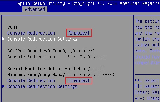
- BIOS setting: Advanced→Serial Port Console Redirection→COM1-Console Redirection Settings & EMS-Console Redirection Settings
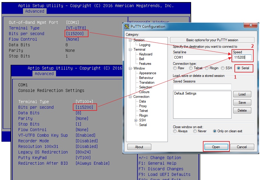
Please set the Putty’ “Connection Type” = Serial, and “Speed” are equal with “Bits per second”, and click “Open”. - Reboot system and Console Redirection has start working.
Console to BIOS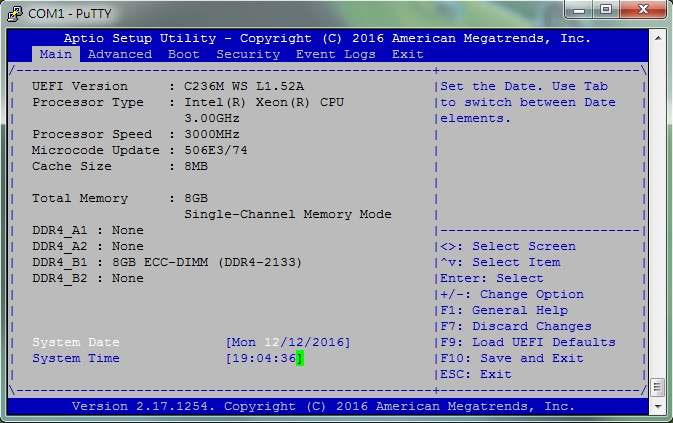
Console to PXE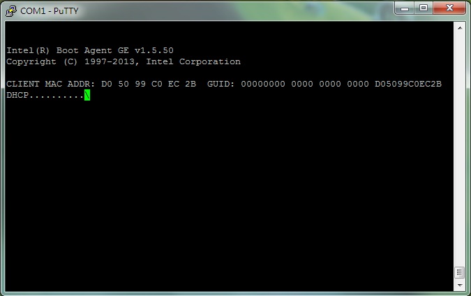
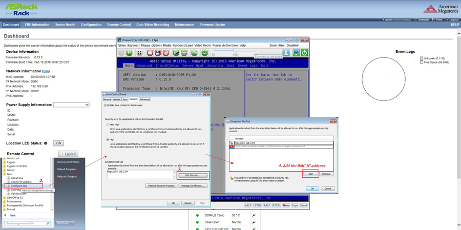
- For Megarac SP Console Redirection does not work on JAVA Version 8 Update 131, kindly rollback to Java version 8 Update 121 for the temporary solution.
We will release the updating BMC FW to website. Please keep track your model' latest BMC FW on our website from time to time. - Setting of Java Version 8 Update 121 to run Console Redirection
- 1. Uninstall the JAVA Version 8 Update 131, and install to Java Version 8 Update 121.Download link:
http://www.oracle.com/technetwork/java/javase/downloads/java-archive-javase8-2177648.html - 2. After Java Version 8 Update 121 installed, open the “Configuration Java”.
- 3. Select “Edit Site List…” from “Security” tab.
- 4. Add the BMC IP address into the Exception Site List.
- 5. Open a new web browser to connect to the Megarac SP and launch the JViewer.
What is Meltdown and Spectre issue
The issue is a new side-channel analysis method developed by external researchers that gathers information by observing the physical behavior of certain processing techniques that are common to modern computing platforms, when operating as designed. Malicious code using this method and running locally on a normally operating platform could infer data values from memory.
Will ASRock Rack release the FW for it?
ASRock Rack has been notified about an industry-wide potential security issue and is taking action to help our customers address their concerns.
- Based on Intel and ASRock Rack current assessment of these exploits we believe that they do not have the potential to corrupt, modify or delete data.
- ASRock Rack is working with Intel to design, test and deploy the appropriate mitigations as early as reasonably possible.
- Firmware mitigations will be available and continue to roll out over the next few weeks.
- For more information please refer to Intel public announcement website:
https://www.intel.com/content/www/us/en/architecture-and-technology/facts-about-side-channel-analysis-and-intel-products.html
Where can I find OS hotfix for it:
Following is the hot fix for each OS.
P.S
Some Linux distributions have more than one update.
For example: CVE-2017-5753 and CVE-2017-5715 is for “Spectre”, CVE-2017-5754 is for “Meltdown”
RedHat /CentOS 6 :
https://access.redhat.com/errata/RHSA-2018:0008
RedHat /CentOS 7:
https://access.redhat.com/errata/RHSA-2018:0007
Ubuntu:
https://wiki.ubuntu.com/SecurityTeam/KnowledgeBase/SpectreAndMeltdown
SUSE:
https://www.suse.com/security/cve/CVE-2017-5753
https://www.suse.com/security/cve/CVE-2017-5715
https://www.suse.com/security/cve/CVE-2017-5754
Debian:
https://security-tracker.debian.org/tracker/CVE-2017-5753
https://security-tracker.debian.org/tracker/CVE-2017-5715
https://security-tracker.debian.org/tracker/CVE-2017-5754
Fedora:
https://fedoramagazine.org/protect-fedora-system-meltdown/
VMware:
https://www.vmware.com/us/security/advisories/VMSA-2018-0002.html
Wind River:
https://www.windriver.com/announces/cve-2015-7547_notice/
If you are using priority Linux, and need to patch by yourself.
Linux patches info is in below website for variant 2 and 3.
https://meltdownattack.com/
P.S
Variant 1 (CVE-2017-5753/) Bounds Check Bypass unless you run 4.9 or later. It doesn't have an eBPF problem.
eBPF is fixed upstream already.
How to update BIOS through Server Management Utility?
(Supports server motherboard built with BMC AST2500 controller)
Preparation
1. Download and install the Server Management Utility.
(Download: http://www.asrockrack.com/support/SMU.asp)
Steps
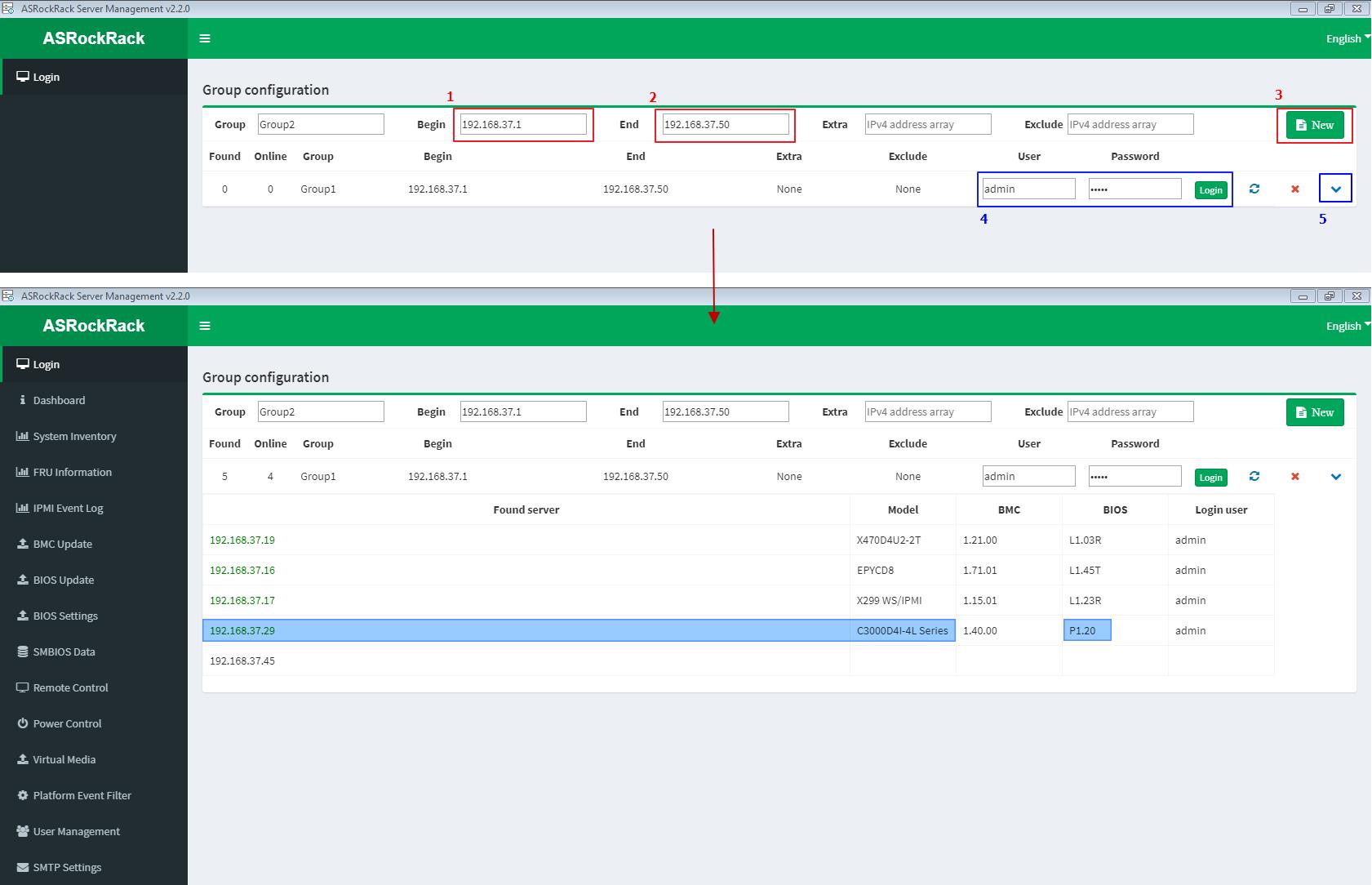
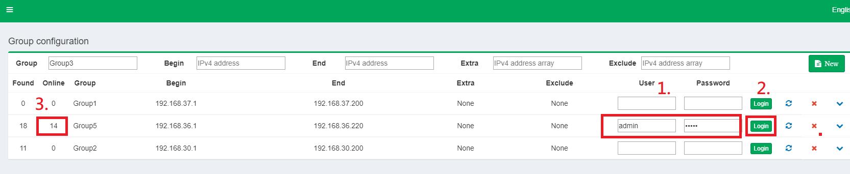
Step 1: Login
1~3: Key-in the IP address range to search out the host machine where need to do the BIOS update procedure.
4~5: Key-in BMC login account, then pull-down to check those searched machines.
(For example: Host machine IP = 192.168.37.29)
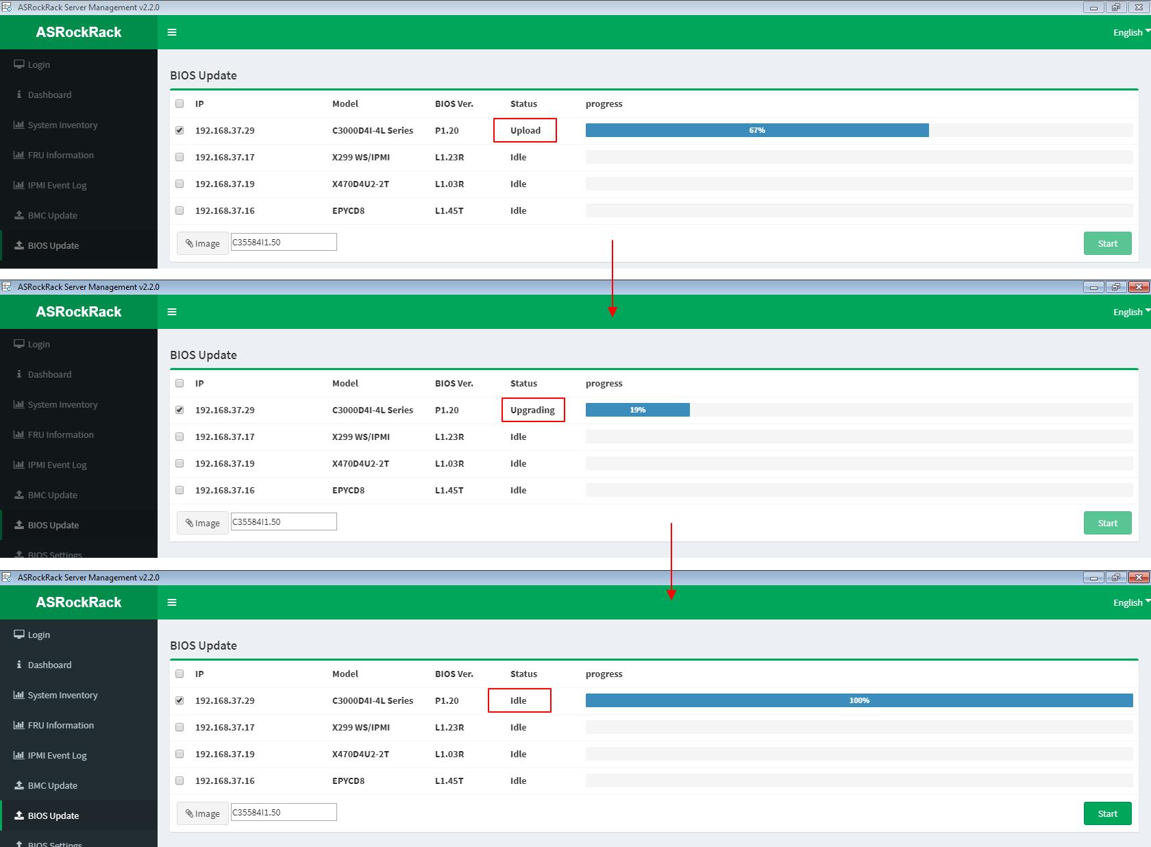
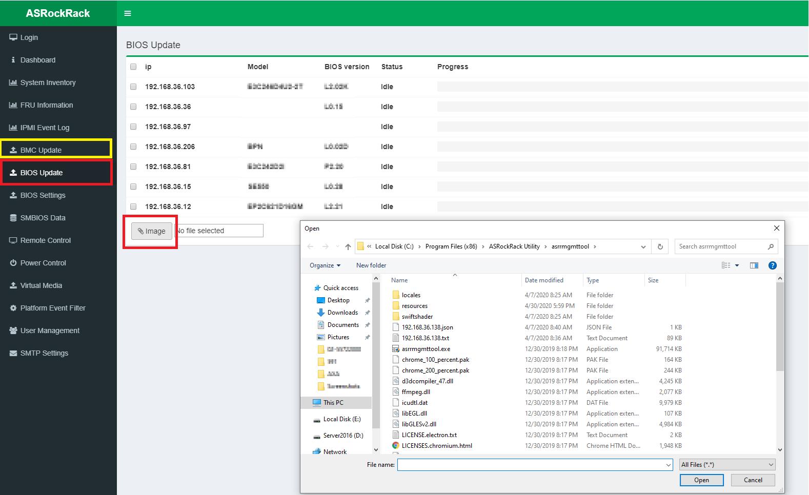
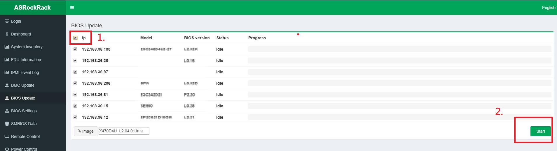
Step 2: BIOS Update
- Tick to select the host machine (ex. 192.168.37.19)
- Import the host machine BIOS image file
- Click “Start” button to start the BIOS update process
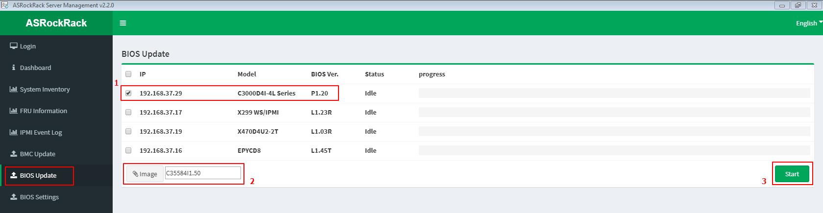
BIOS update is processing with procedures [Upload --> Upgrading --> Idle]
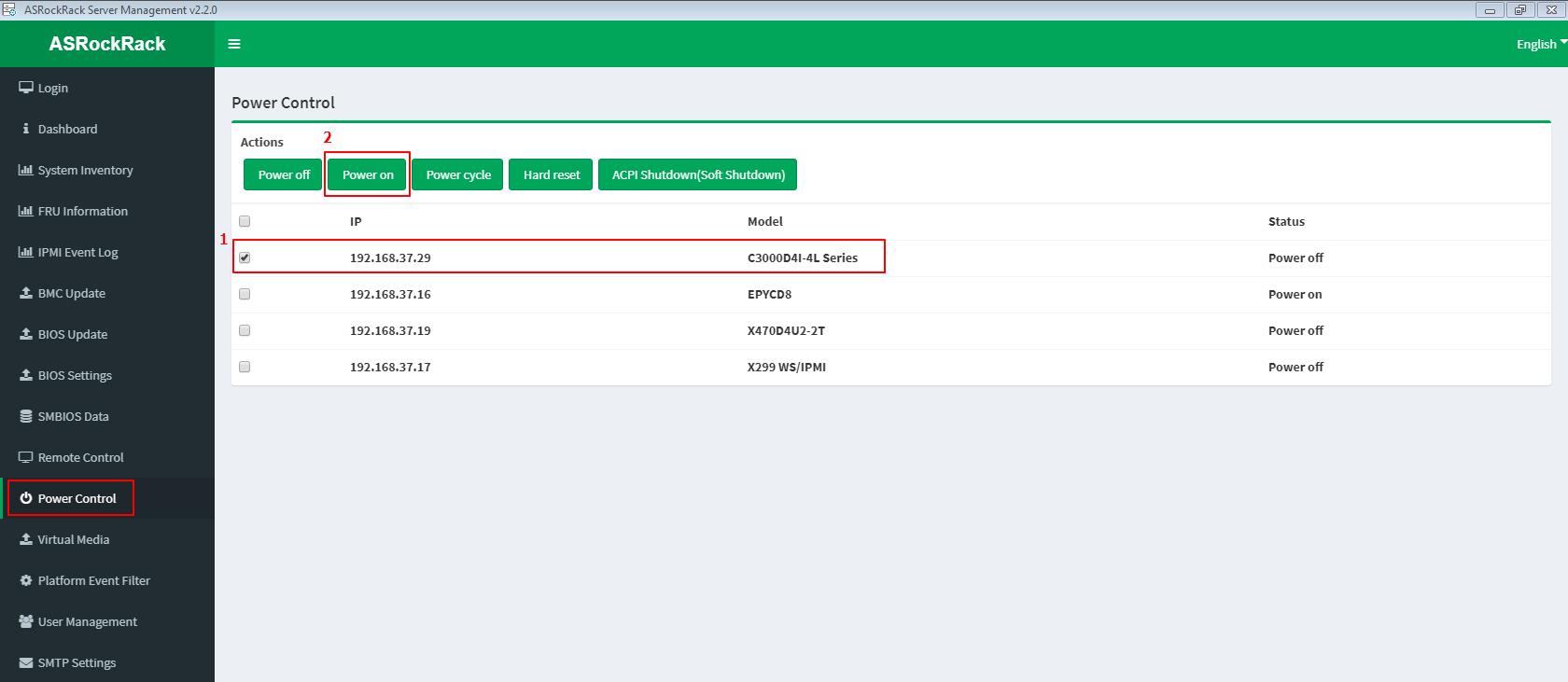
Step 3: Power ON/Reboot system remotely
- Tick to select the host machine IP (ex. 192.168.37.19)
- Click “Power on” (“Hard reset” if for reboot)
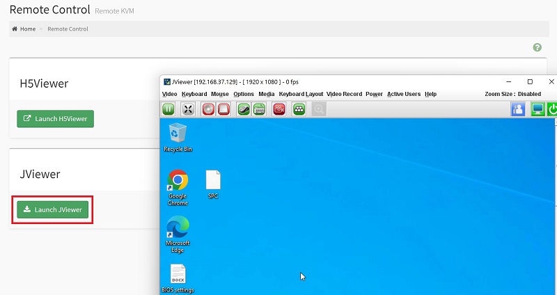
Step 4: Remote control system
- Select the host machine (ex. 192.168.37.19)
- Click “Launch JAVA KVM”
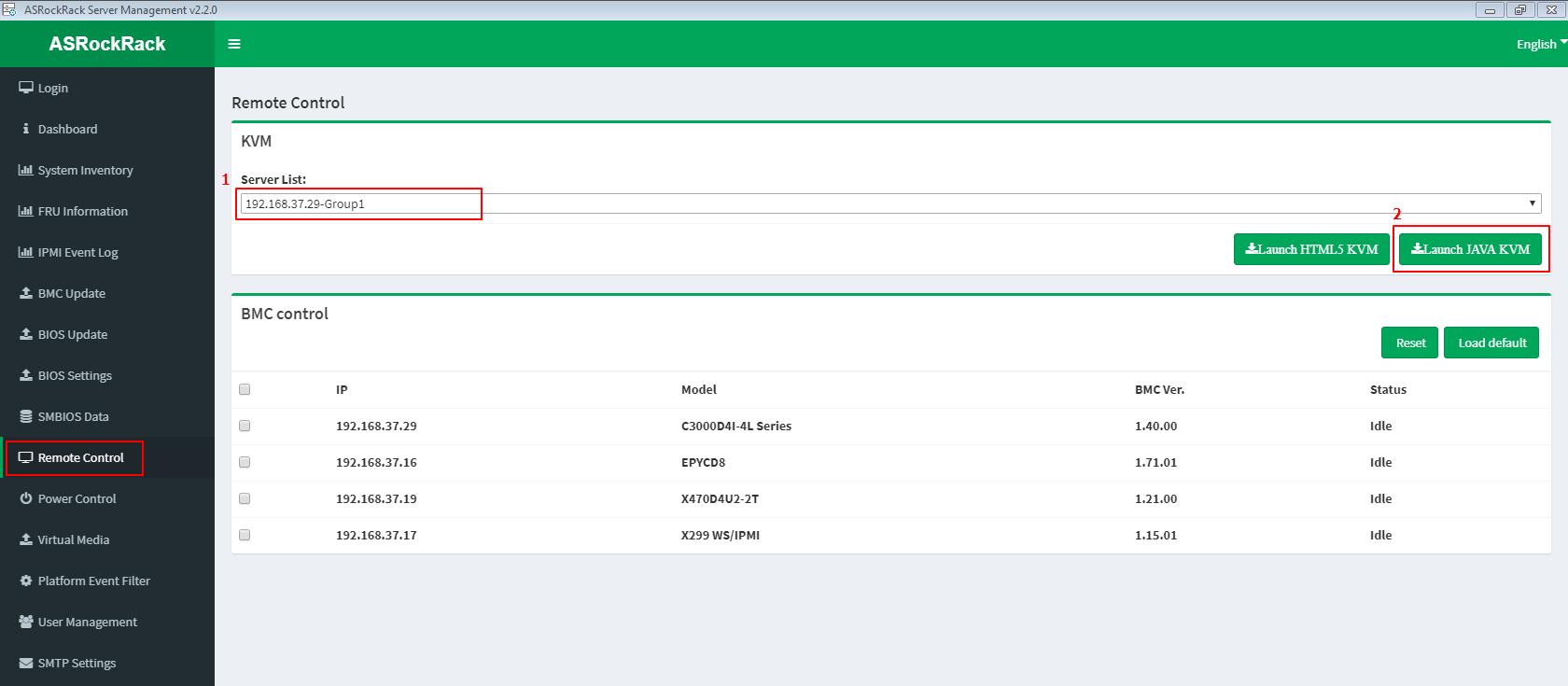
- Remote the host machine by Jviewer. And check to whether the BIOS update process is success or fail.
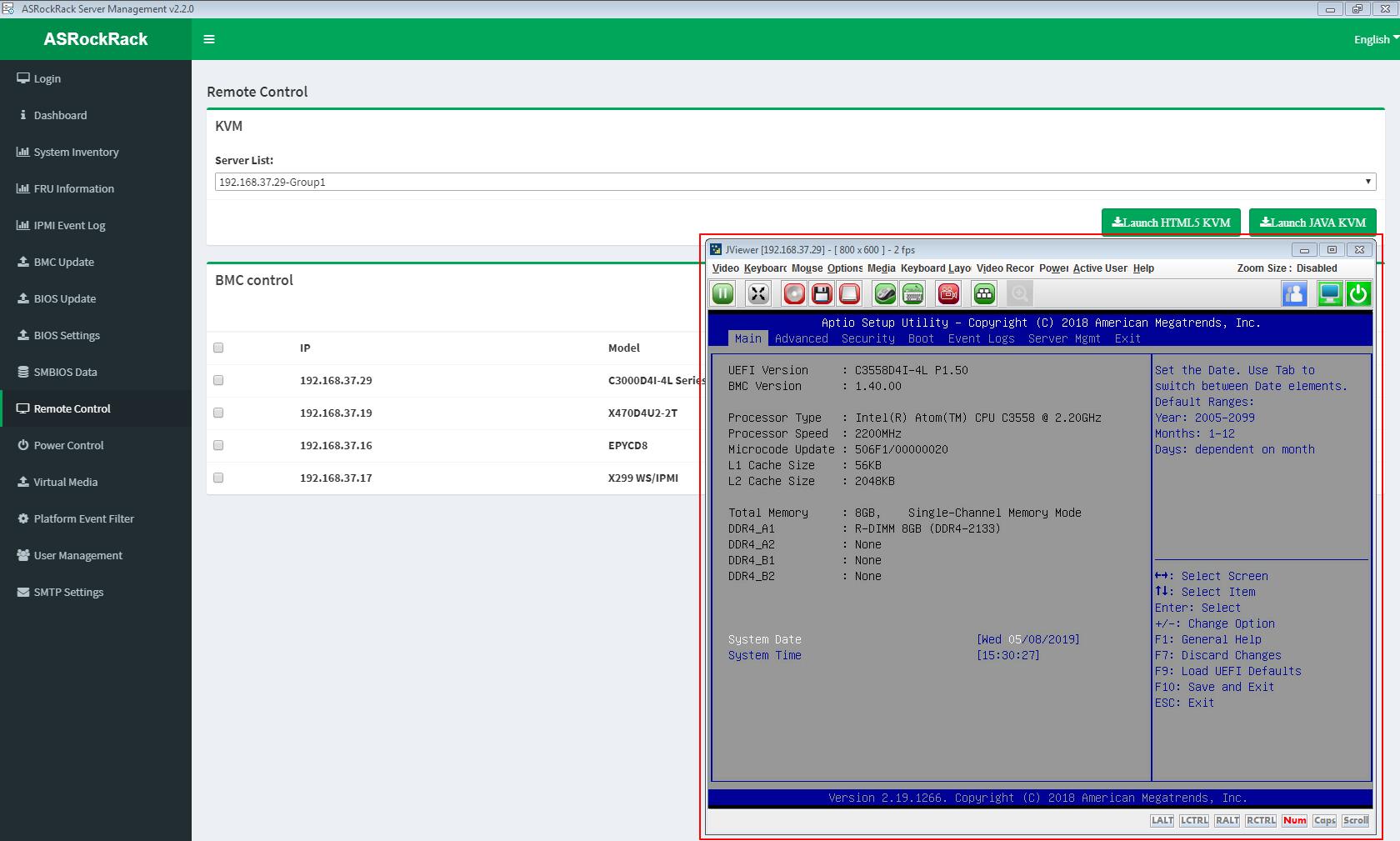
Step 5: Back to Step 1: Login
Check to the latest BIOS version of the host machine.
(For example: Host machine IP = 192.168.37.29)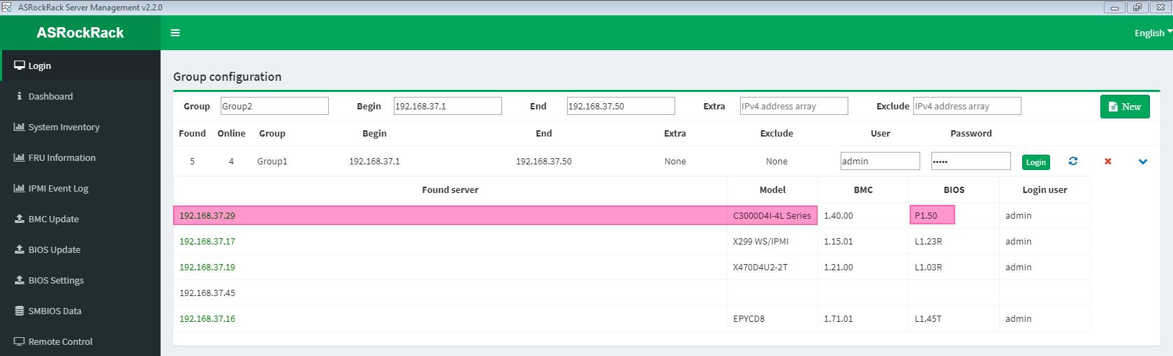
Steps to update BIOS firmware via IPMI webUI
(Supports server motherboard built with BMC AST2500/AST2600 controller)
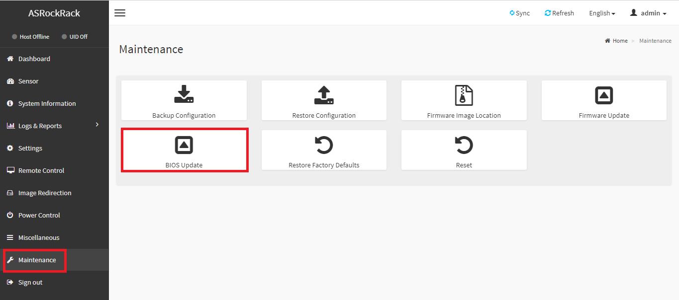
BIOS Firmware Update
[Maintenance] -> [BIOS Update]
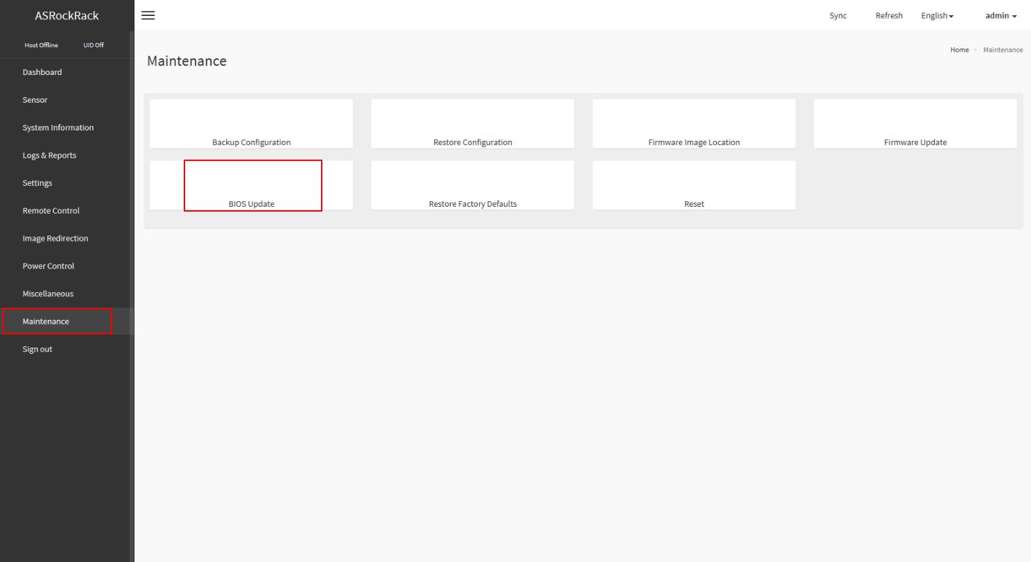
This wizard will takes you through the process of firmware upgrades.
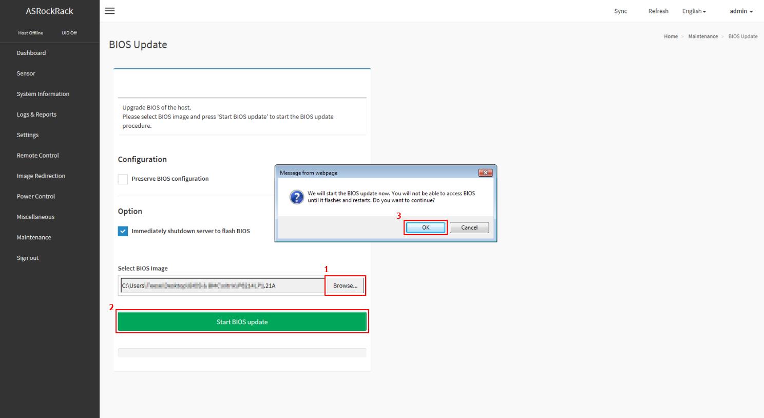
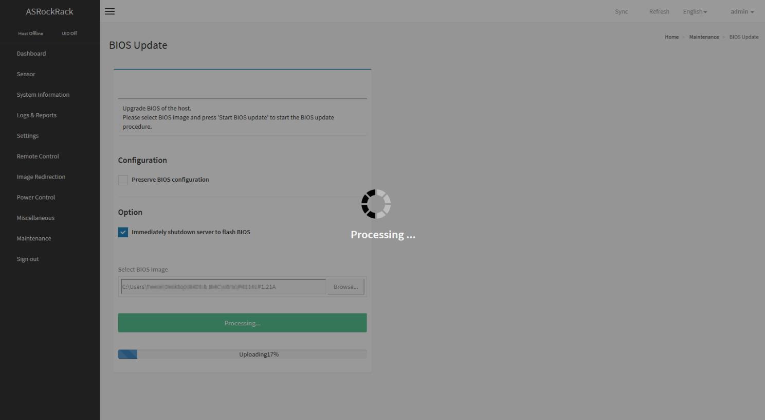
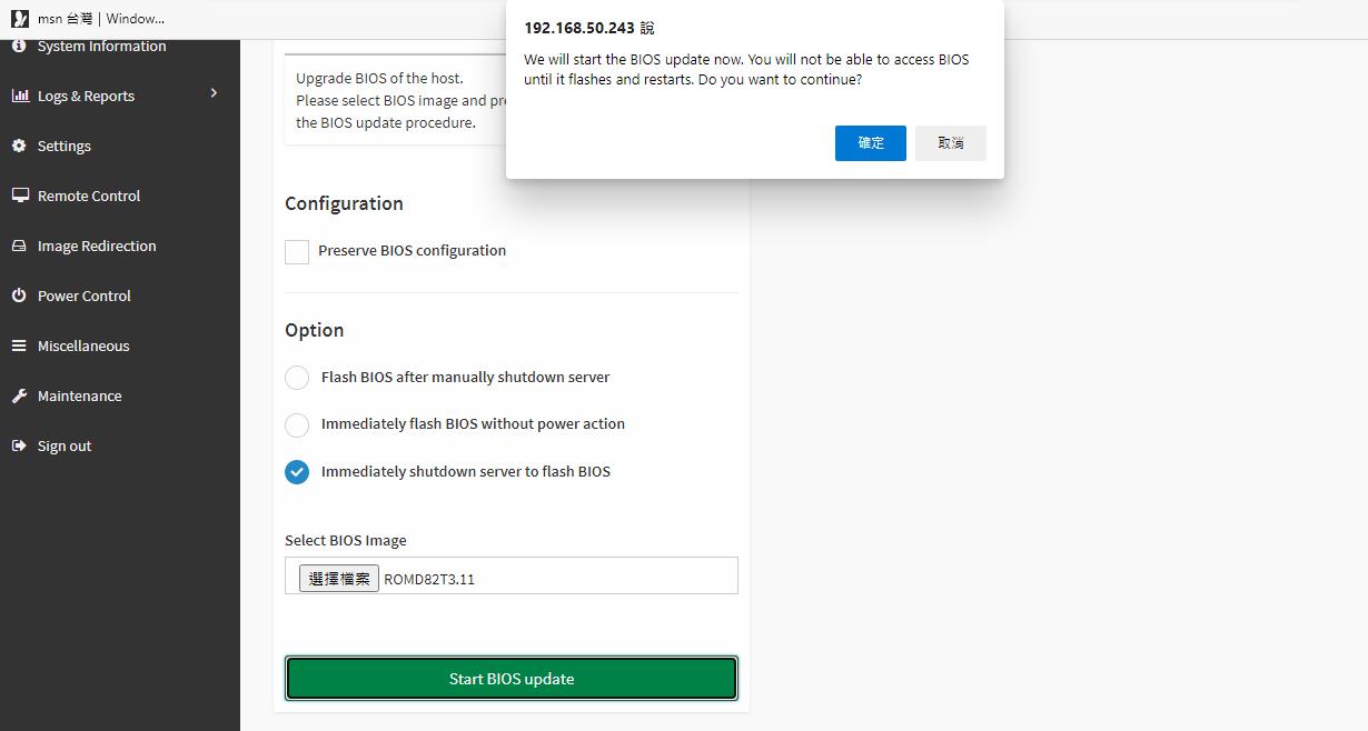
Click the “Browse...” to select the BIOS FW file. Then click “Start BIOS update” for the upgrade process. And click “OK” if confirmed to continue the process.
FW verification processing, please wait a few second..
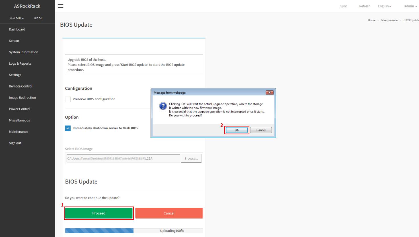
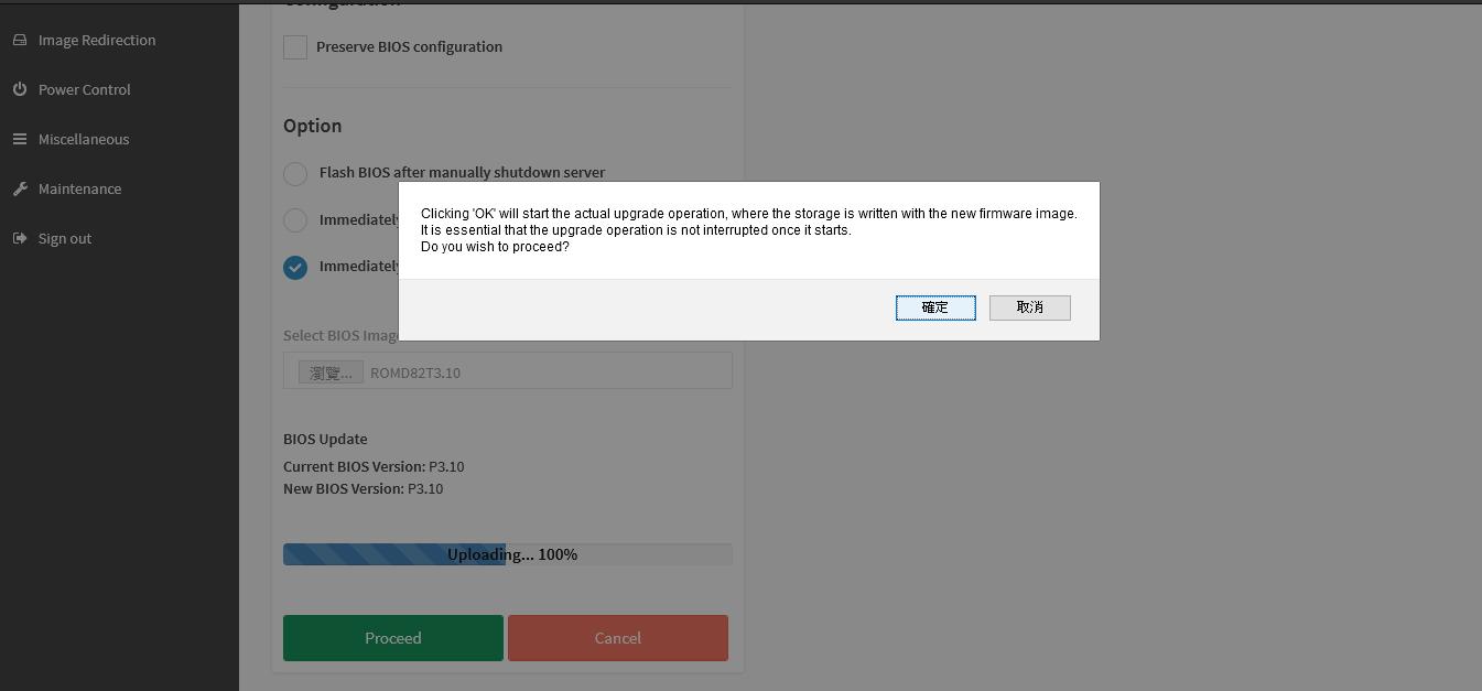
Click “Proceed” to continue the BIOS FW upgrade process. Then click “OK” to start the actual BIOS FW upgrade operation.
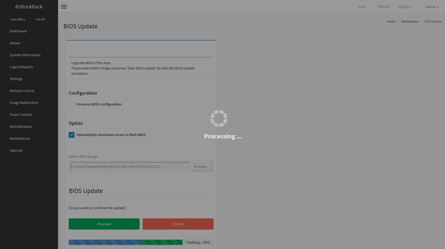
FW updrage is processing, please wait a few second..
BIOS FW upgrade process finished. Click “OK” to reload the webpage.
Remark: Clear the browser cookies after the BIOS FW upgrade process finished.
Steps to update BMC firmware via IPMI webUI
(Supports server motherboard built with BMC AST2500/AST2600 controller)
BMC Firmware Update
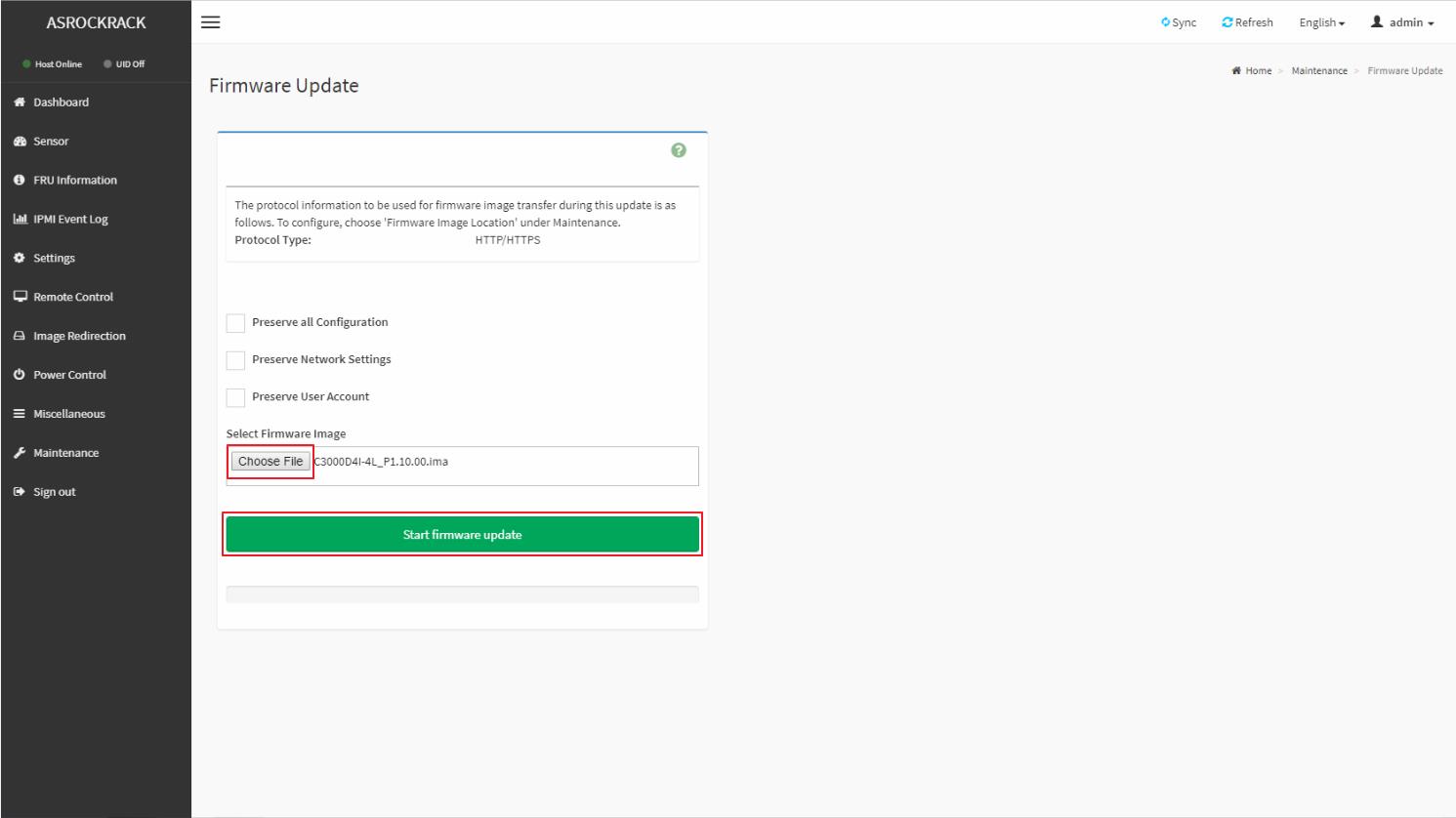
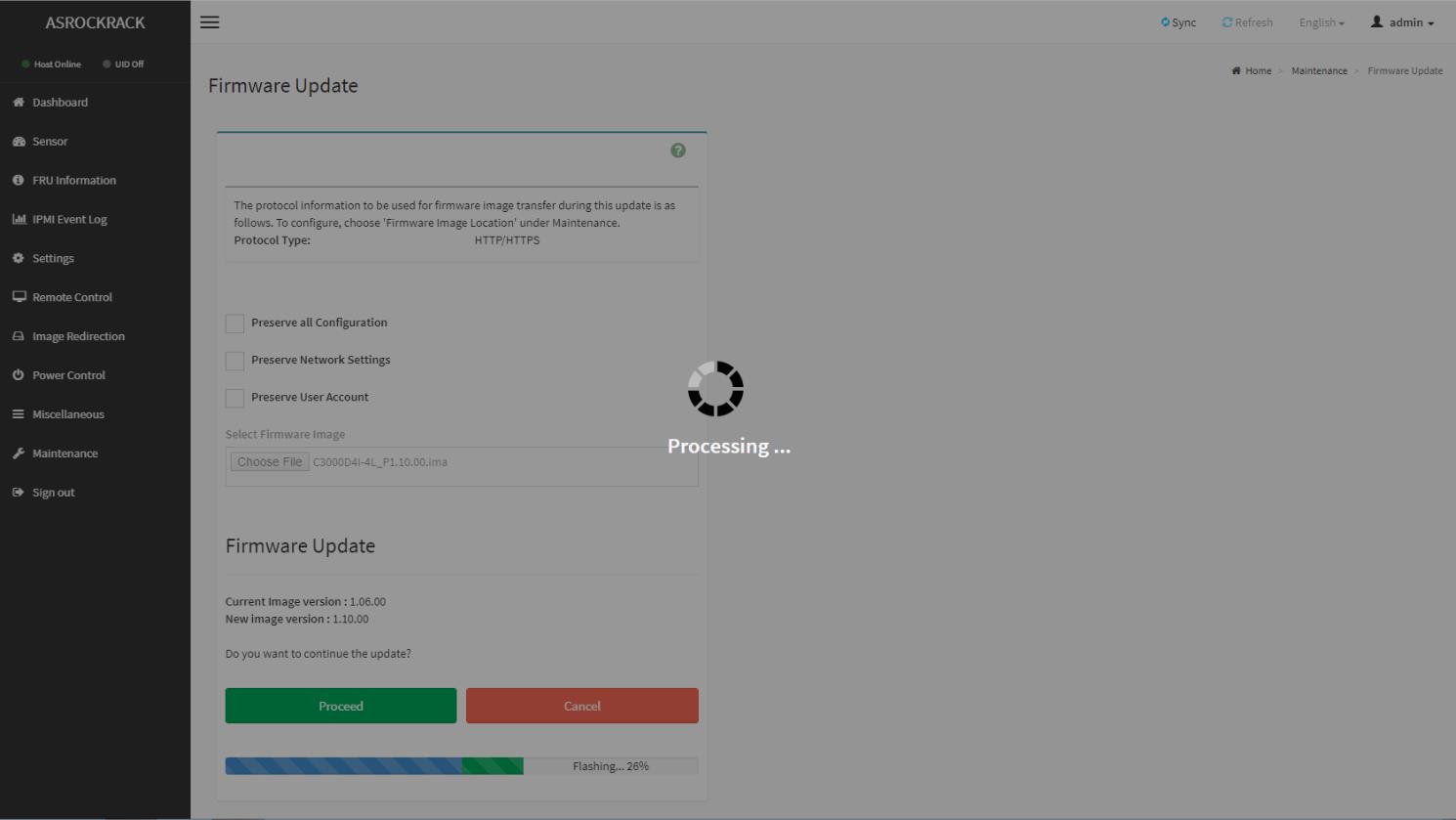
[Maintenance] -> [Firmware Update]
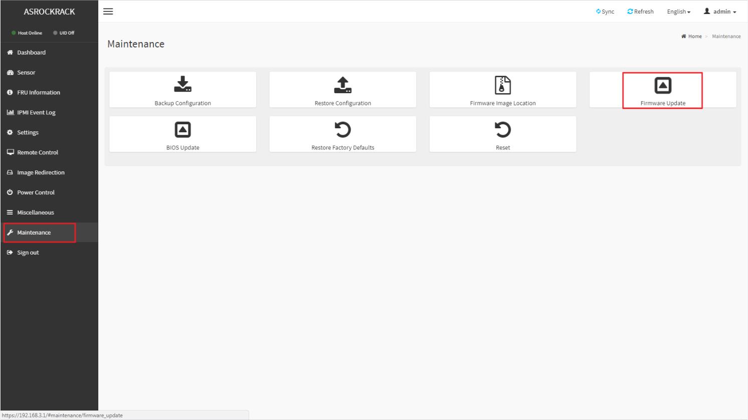
This wizard will takes you through the process of firmware upgrades.
Click the “Choose File” to select the BMC FW file. Then click “Start firmware update” for the upgrade process.
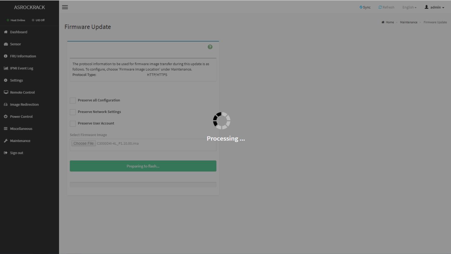
FW verification processing, please wait a few second..
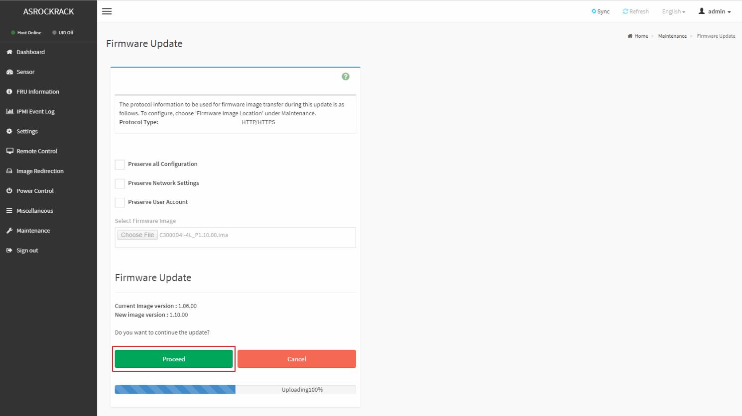
Click “Proceed” to continue the BMC FW upgrade process.
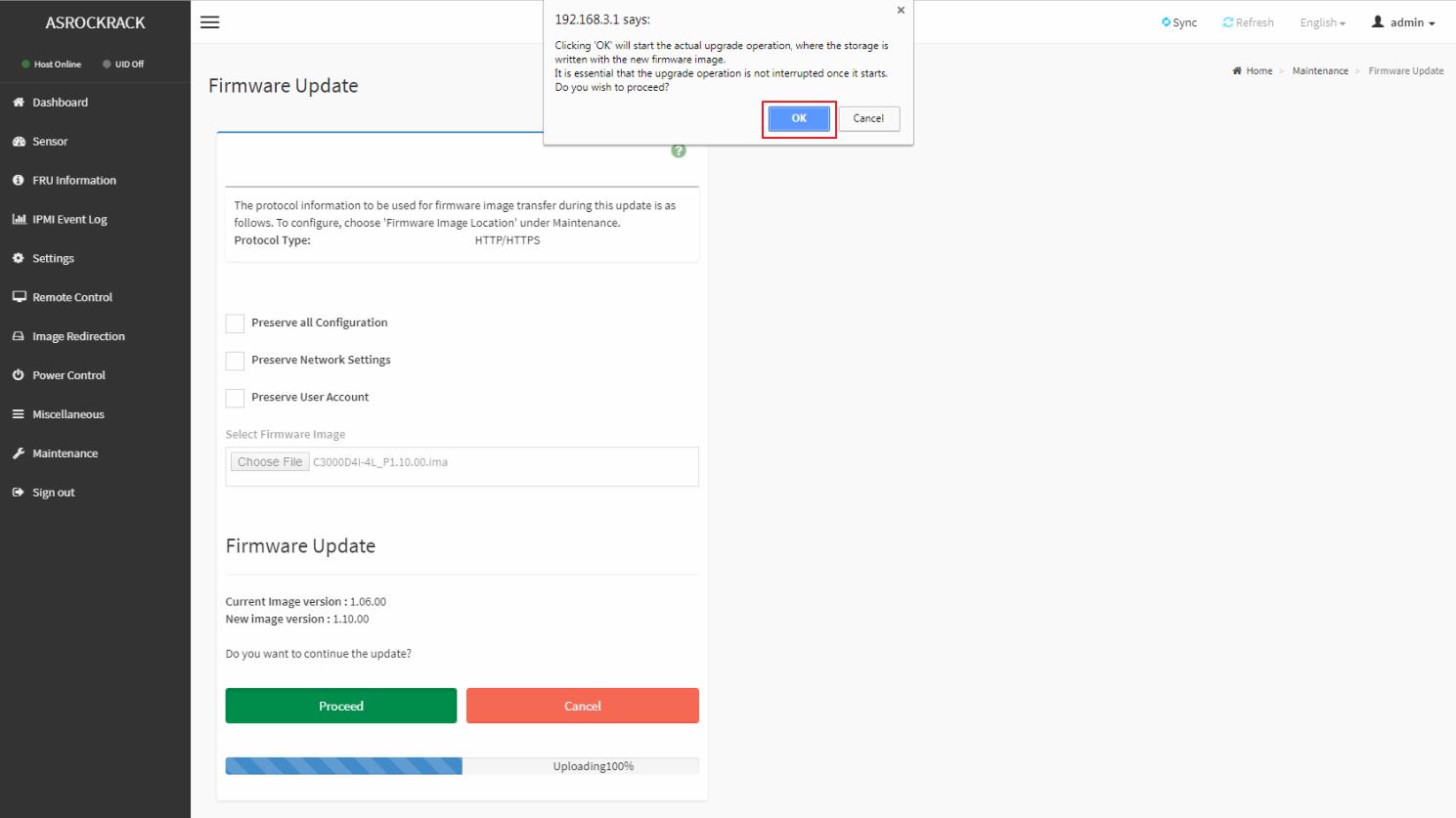
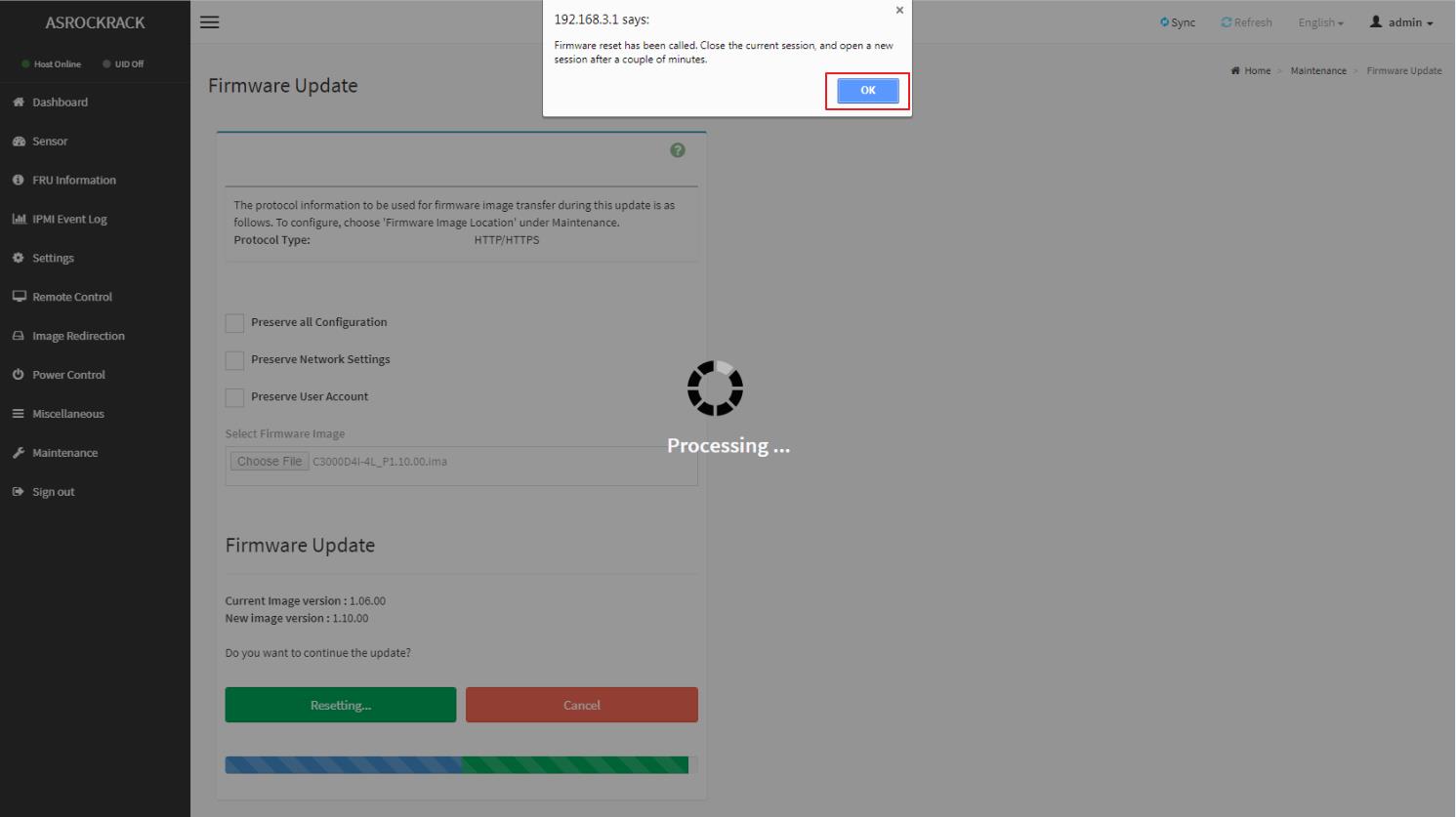
Click “OK” to start the actual BMC FW upgrade operation.
FW updrage is processing, please wait a few second..
BMC FW upgrade process finished. Click “OK” and reboot the system.
Remark: Clear the browser cookies after the BMC FW upgrade process finished.
Preparation:
Server Management Utility (asrrmgmttool): http://www.asrockrack.com/support/SMU.asp
Steps:
1. Download and install the asrrmgmttool
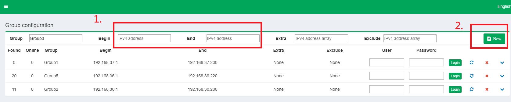
2. Open asrrmgmttool application
3. Enter the IP address range of the systems you want to update, and click “New”
4. Chose the “Refresh” icon and wait for the process
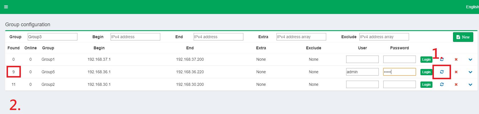
5. Enter the User/Password, and click “Login”. After login you should see the online system.
6. Chose to BIOS/BMC Update, and select the BIOS/BMC image need for the updating
7. Select the system IP that need for update the BIOS/BMC FW, and click “Start” to proceed
8. Wait for the FW upload and upgrade process
Uploading/Upgrading process
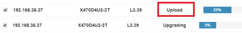
Idle and 100% means upgrade process has completed
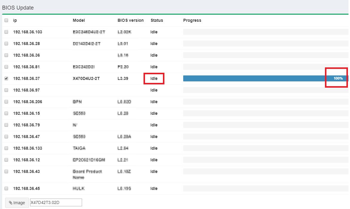
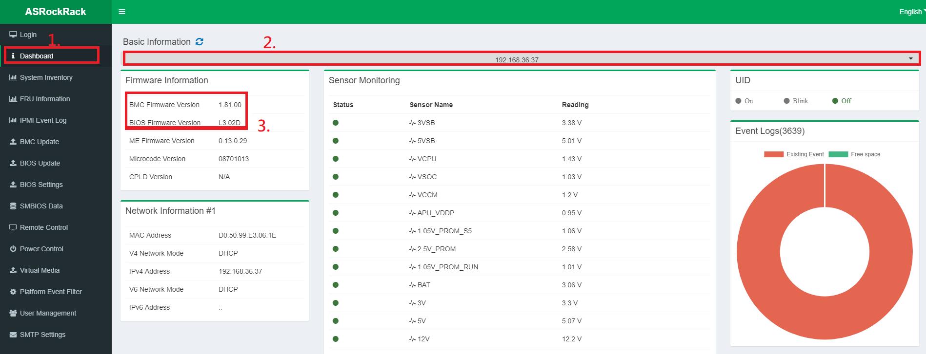
9. Wait for 1~3 minutes, then you can recheck to the system updating BIOS/BMC version
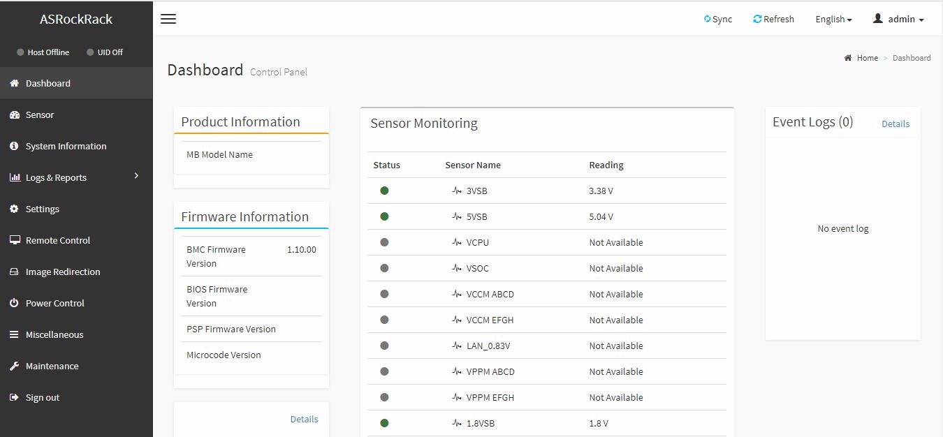
[1]click Dashboard >> [2]select the IP address >> [3]check BIOS/BMC version
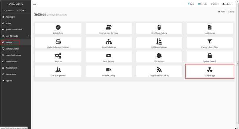
1. Login to IPMI webUI > Settings > FAN Settings
2. Chose Open Loop Control Table, then set your customize fan table and save.
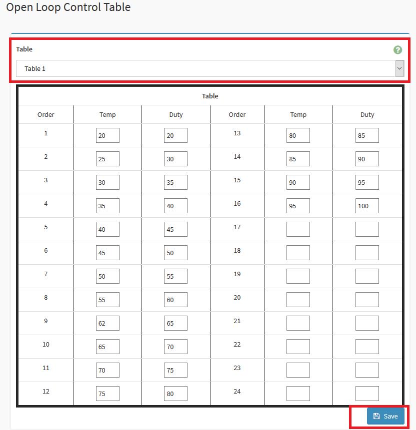
Sample Desc: Assuming the above Open Loop Fan Table is for CPU temperature sensor, when the CPU temperature reaches between 20~25 degrees, the fan duty will be at 30%. If CPU temperature reaches 57 degrees, fan duty will be at 60%.
3. Chose Close Loop Control Table, then set your customize fan table and save.

Sample Desc: Assuming above Close Loop Fan Table is for CPU temperature sensor, when the CPU temperature is higher than 60 degrees, the fan duty cycle will increase at a rate of 1% per second; when the CPU temperature is lower than 50 degrees, the fan duty cycle will decrease by 1% every 5 seconds.
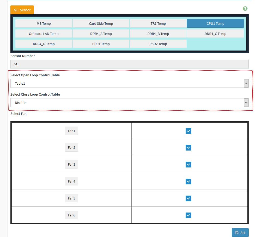
4. Go to IPMI webUI > Settings > FAN Settings > Temperature Sensor and Corresponding Fan Table
5. Chose the sensor and fan table you want to base on. And select the fan which will follow the rule.
For example, the following screenshot setting is
FAN1~6 will base on CPU1 temperature and follow to FAN table 1 which from the “Open Loop Control Table”.
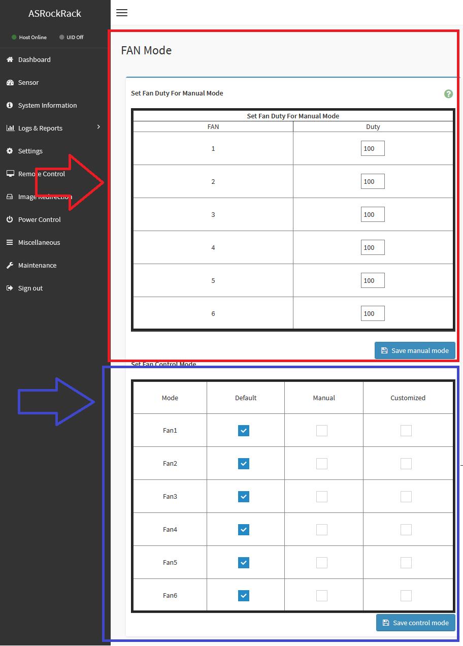
6. Go to IPMI webUI > Settings > FAN Settings > FAN Mode
7. Select different fan mode
Customized mode
If you want to let the fan to follow fan table
You will need to modify the fan you need to customized mode as following blue frame then save control mode
Manual mode
If you want to set fan to static mode, you need to set fan duty as following red frame first, then save manual mode
Second, select which fan you need in manual mode as following blue frame then save control mode
 The format of our documents are in PDF files. If you have not installed Adobe Acrobat Reader, please get it from Adobe.
System Remote Control Quick Start Guide(PDF)
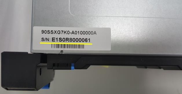
1. The Serial Number for your product is located here:
I. For systems/ barebones:
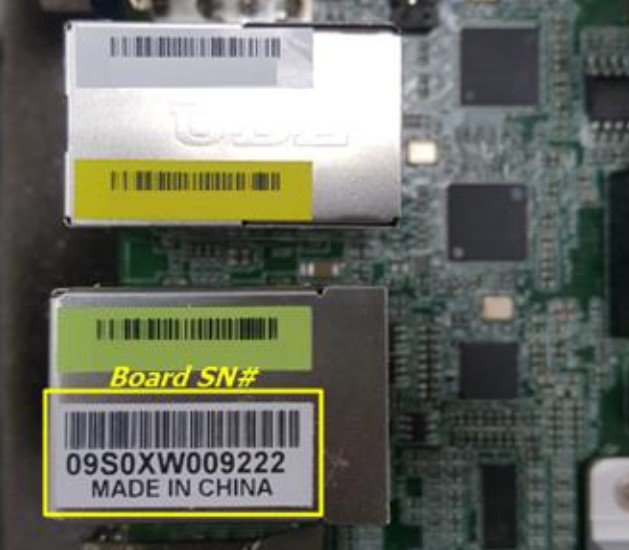
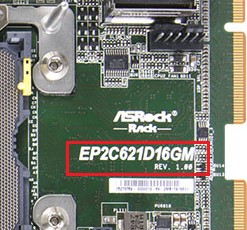
II. For motherboards:
2. Motherboard Model and H/W Rev. could be found on the board itself:
e.g. Motherboard Model = EP2C621D16GM, H/W Rev. = 1.00
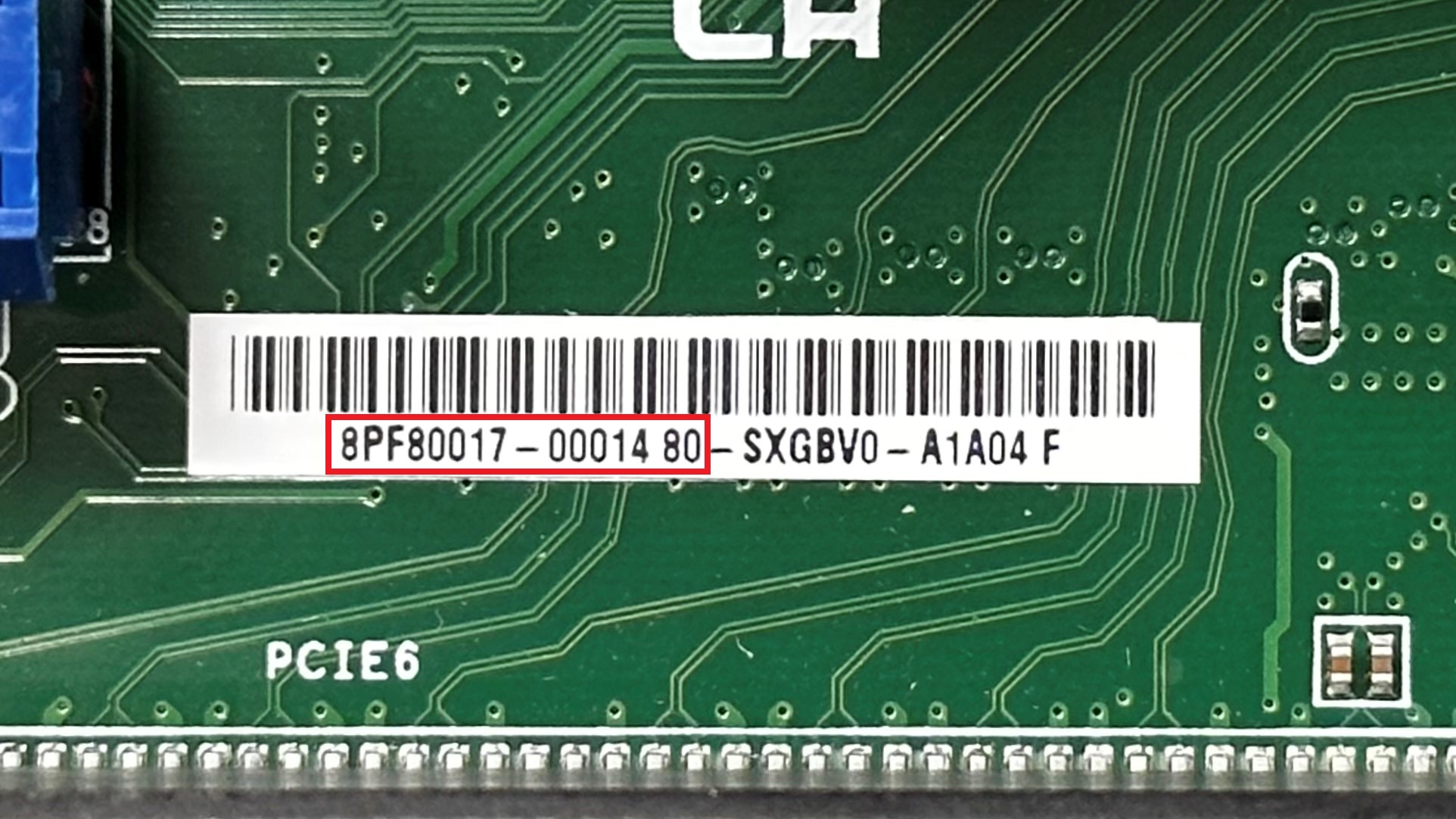
3. Motherboard PPID is optional if you have the S/N numberyou’re your product. If the S/N number of the motherboard is missing, please find the white label on the board and key in the part framed in red.
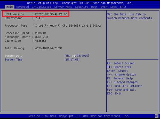
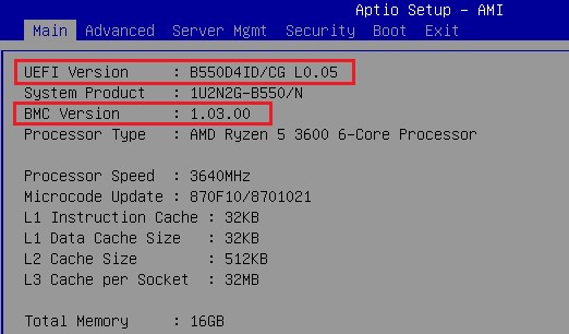
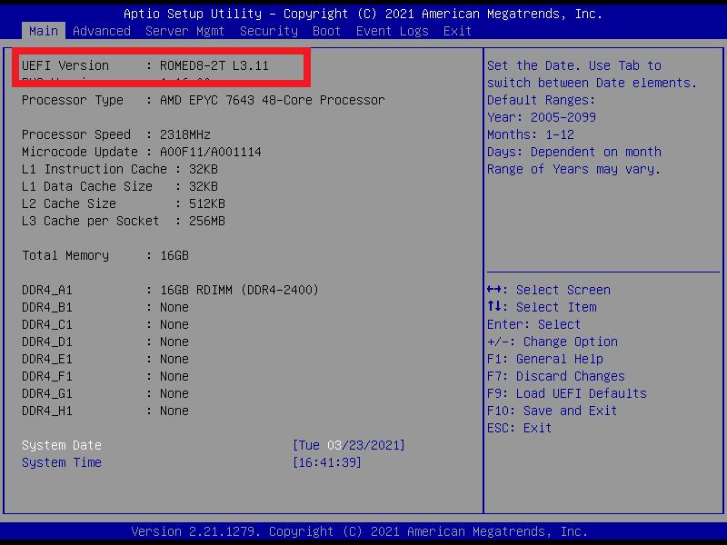
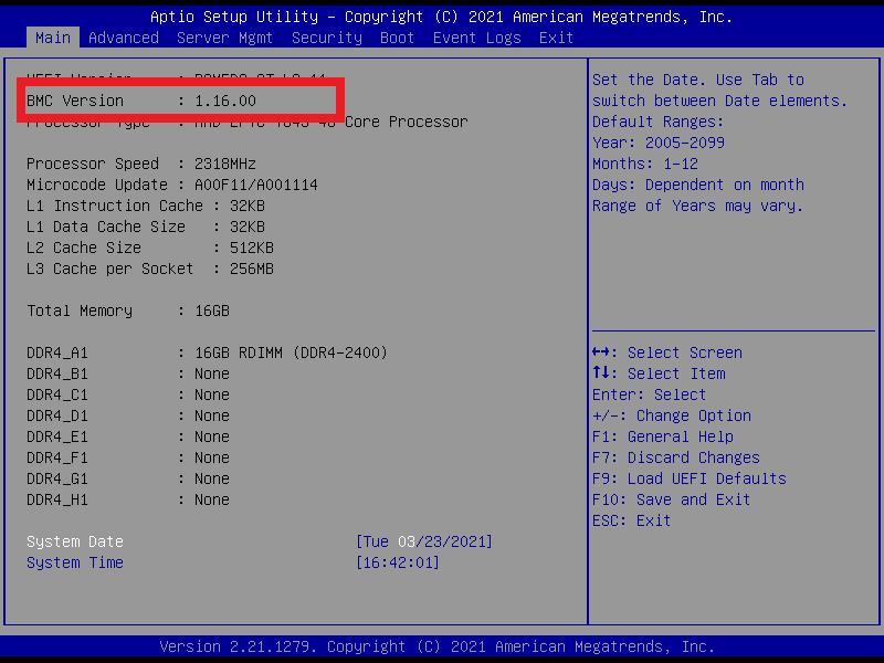
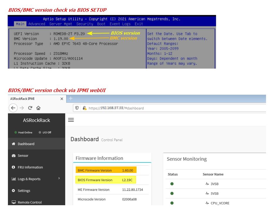
4. BIOS version (UEFI Version) and BMC version could be checked in BIOS Main page:
1.Update BIOS FW
Step1. Login to IPMI Web UI
Step2. [Maintenance] -> [BIOS Update]
Step3. This wizard will takes you through the process of firmware upgrades.
Click the “Browse...” to select the BIOS FW file. Then click “Start BIOS update” for the upgrade process. And click “OK” if confirmed to continue the process.
Step4. FW verification processing, please wait a few second..
Step5. Click “Proceed” to continue the BIOS FW upgrade process. Then click “OK” to start the actual BIOS FW upgrade operation.
Step6.FW updrage is processing, please wait a few second..
Step7. BIOS FW upgrade process finished. Click “OK” to reload the webpage.
Remark: Clear the browser cookies after the BIOS FW upgrade process finished.
2. Update BMC FW
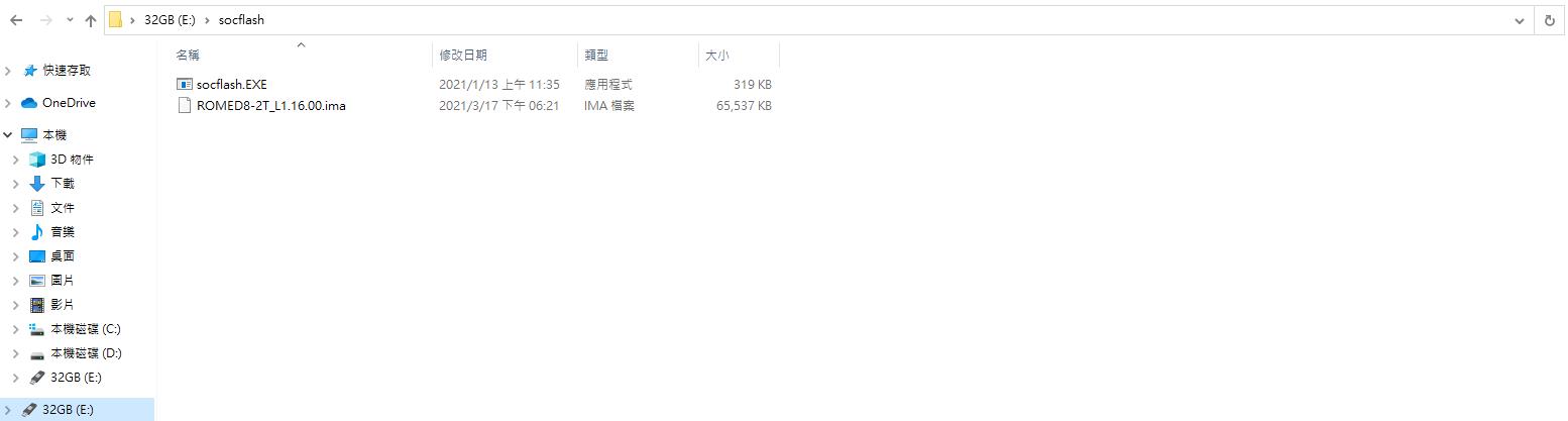
Step1. Prepare a flash drive, put the tool of socflash (such as the compressed file of attachment) and the ima file to be updated
Socflash Tool download link https://download.asrock.com/TSD/socflash%20v1.20.00.zip
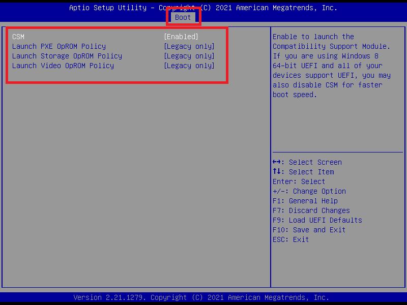
Step2. Before using Socflash tool to update, please enter the BIOS, press "F9" to load default, then press "F10" to save and exit the BIOS, and make sure [CSM] is set to [Enabled]
Step3. Enter DOS and execute " Socflash if=filename option=r "
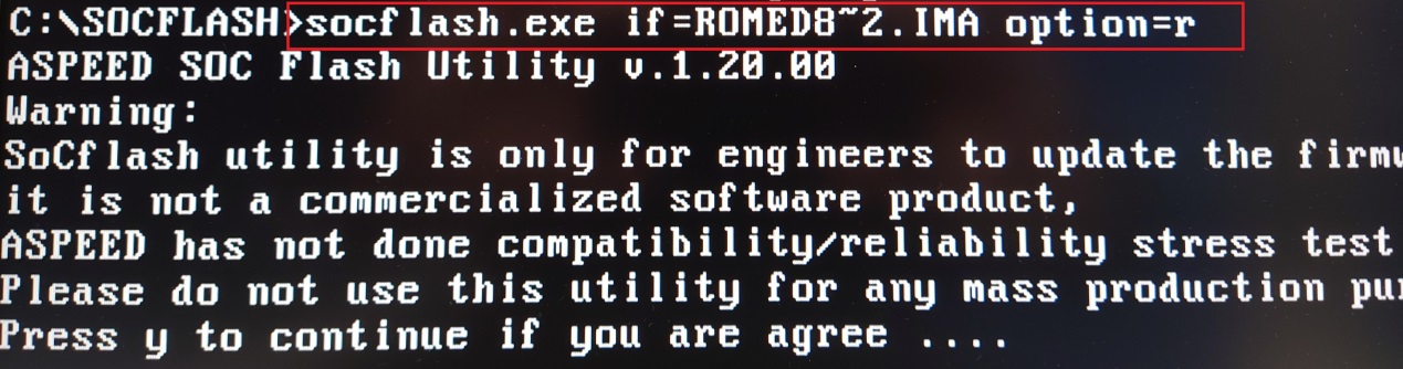
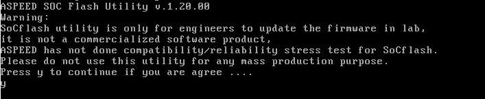
Step4. You will see the last line "Press y to continue if you are agree …." please press y to continue.
Step5. When "update flash chip ok" message appear, it means the update is completed, Please use "Ctrl+Alt+Delete" to restart the system.
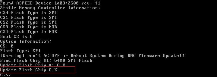
Step6. Go to the BIOS home page to check if the BMC version has been updated
Remark: After the completion of the update will automatically restart the machine several times, this is a normal phenomenon
Step7. Finish
Steps:
Clear the CMOS !. you need to:
1. Disconnect the system power cable
2. Remove the CMOS Battery
3. Press the power button to drain residual energy
4. Touch/short the 2 points/pads on the CLRMOS pad with a paperclip for at least 5 seconds.
Sample the shape of the Clr_cmos pad:
5. Power on and re-check to the system.
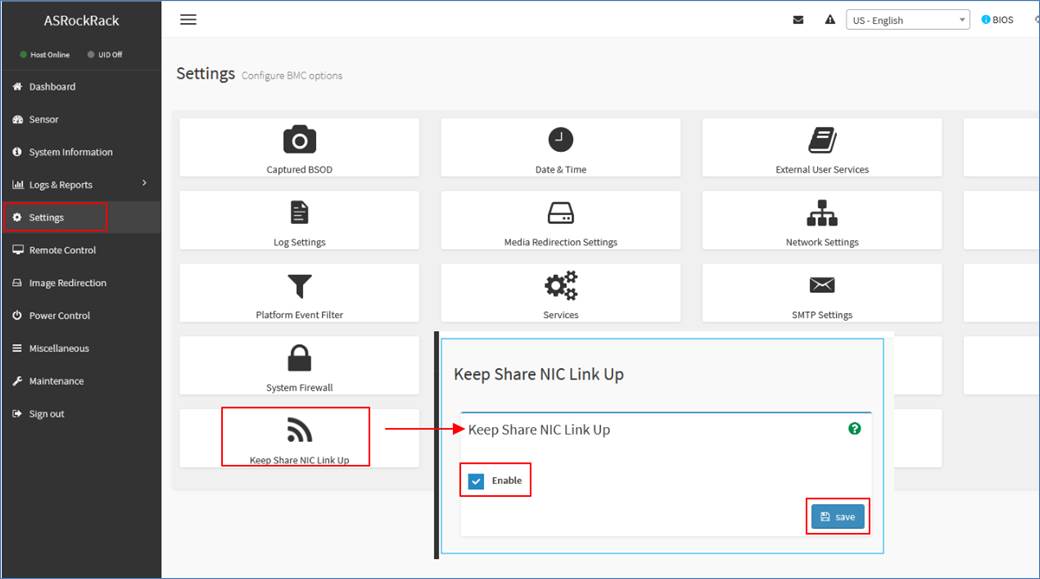
If your access to BMC Jviewer iKVM (Launch Java KVM) with NCSI port connected but encountered the intermittent connection issue, please try to enable the “Keep Share NIC UP” setting.
IPMI webUI -> Settings -> “Keep Share NIC UP” -> tick “Enable” and saved.
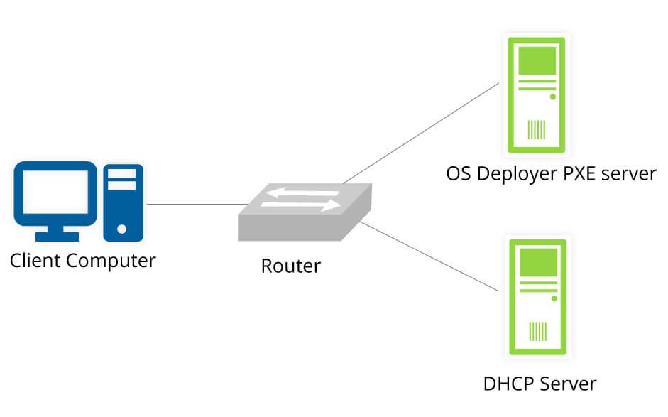
Preparation:
Booting into OS with PXE is to accomplish a non-USB/disc boot by utilizing a PXE server and Internet. First, a PXE server should be established beforehand.
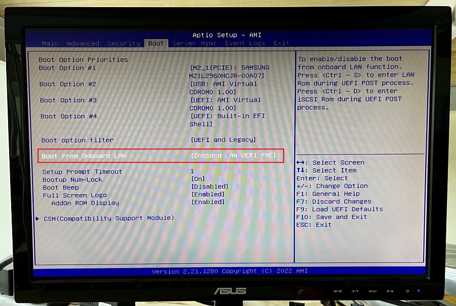
Step:
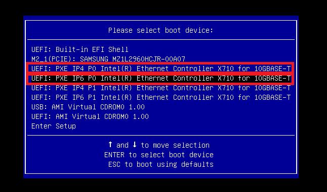
- Go to BIOS menu on the client computer you wish to boot OS on, enable PXE booting option. For this instance, it is the “Boot from onboard LAN”.
- Connect the client motherboard to PXE server with LAN, reboot the system and go to boot menu. Select the option with the very port that the LAN is plugged in. For this instance, it is the “UEFI: PXE IP4 P0”.
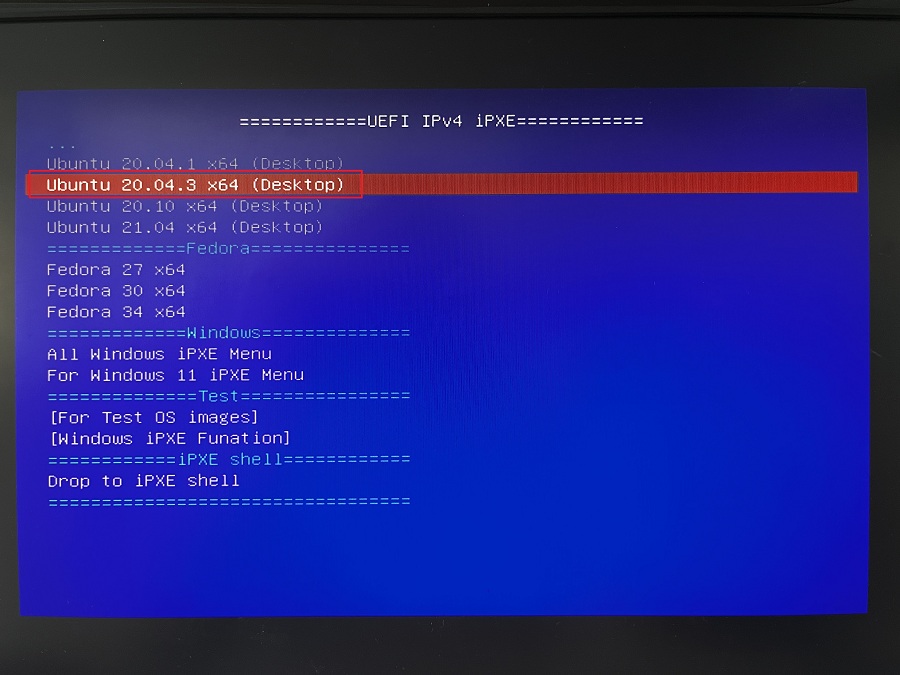
- Then the list of available OS to boot in should show. I chose to boot in Ubuntu 20.04.3 x64 for this instance.
- Wait until the booting process finishes, the OS should work properly via PXE server now.
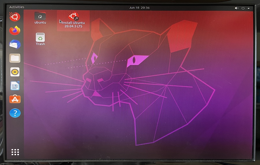
Done!
Preparation:
An IPMI-capable device (Client) to remotely manage and establish connection to the very system with AST2500 (Host).

Find out the domain [IP address] of the host system by checking on the boot process.
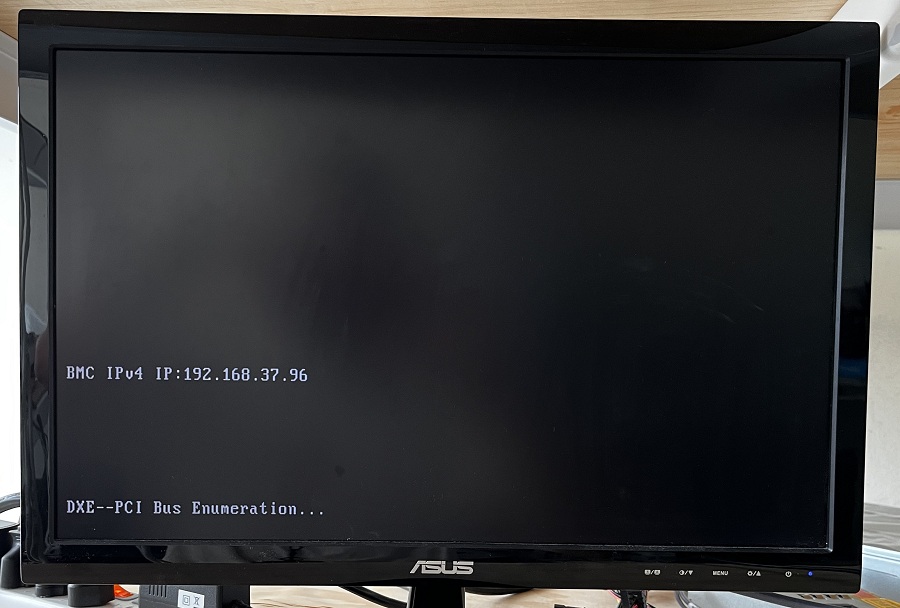
Make sure the host system has the correct LAN port (Dedicated IPMI) connected so that the client could access to it.
Step:
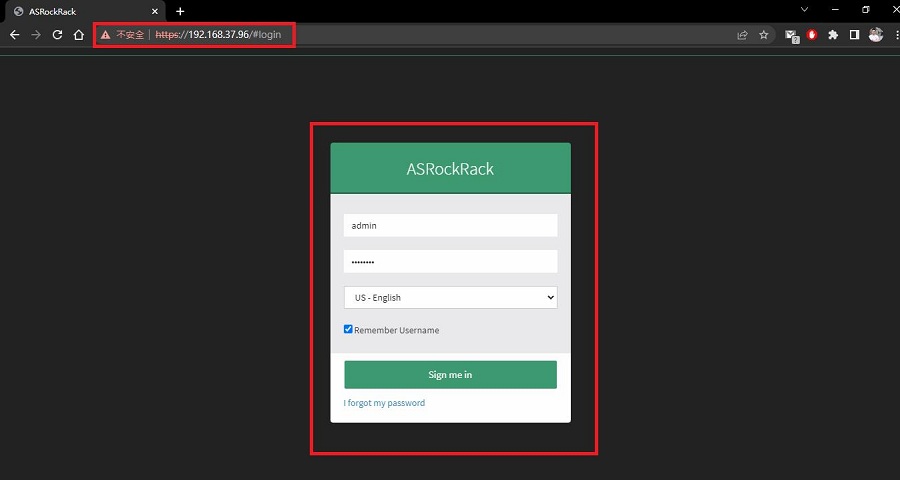
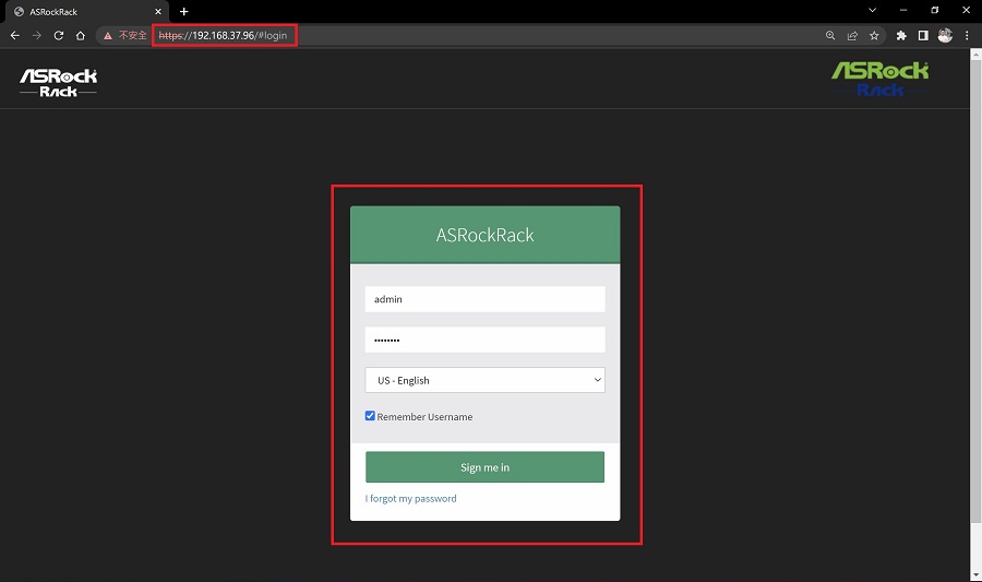
- Access HTML5 Web GUI using IE or chrome browser with the link https://[IP address] , and log in using IPMI user under the right domain.
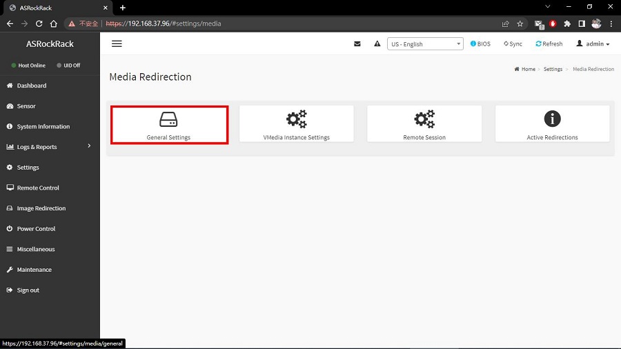
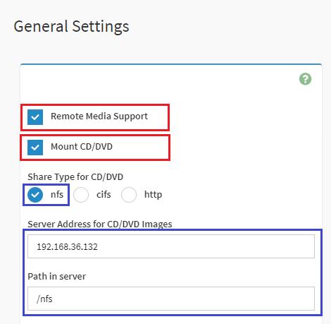
- To access remote media, go “Settings > Media Redirection Settings > General Settings”, tick the “Remote Media Support” and “Mount CD/DVD” boxes. For “Share Type for CD/DVD”, choose “nfs”.
Then input info as the following picture and click save.*Note that choosing “nfs” here and the information framed in blue below is for this instance only. The content should differ by different circumstances.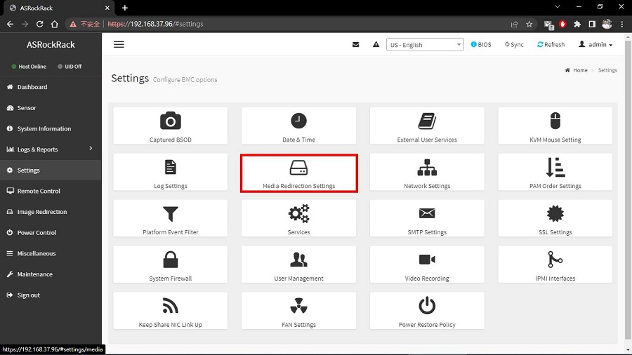
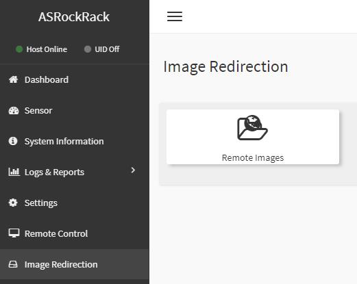
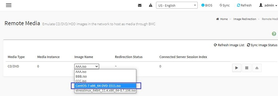
- After enabling the access, go “Image Redirection > Remote Images”. Now you shall be able to view all remote media that is accessible. Choose “Cent OS-7-x86” and click the Play button.*Again, choosing Cent OS is only for this case. This method doesn’t confine the OS types wished to be installed.
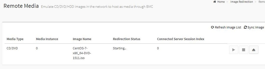
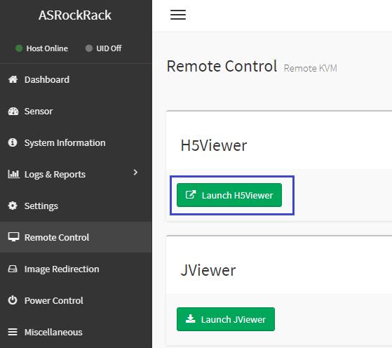
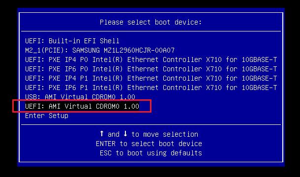
- After the redirection completes, reboot the host system. Go to “Remote Control”, select a viewer to monitor the process. When the LOGO screen shows up, press F11 and choose “UEFI: AMI Virtual CDROM” to start the install procedure.
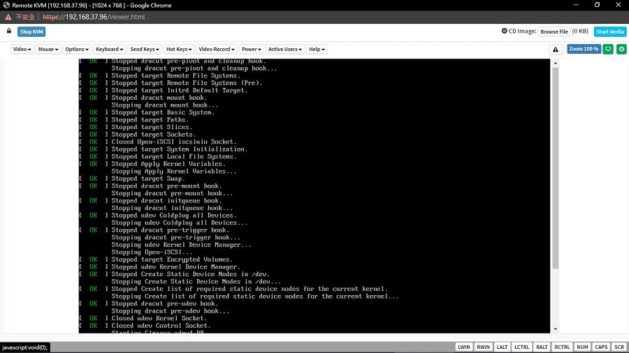
- Be patient as the mounting and installing proceeds, few minutes later you will have this AST2500 platform installed with Cent OS.
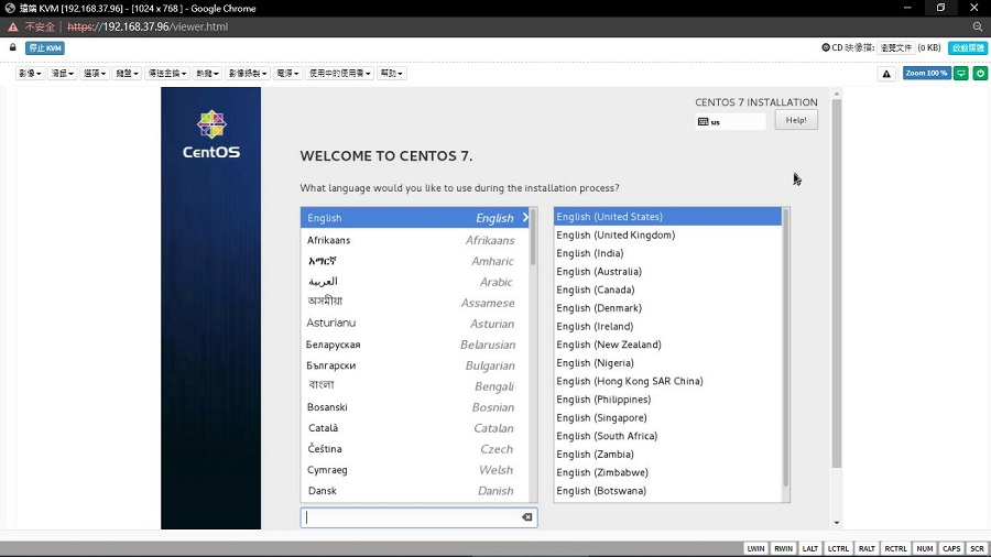
- Follow the procedure and the installation shall be completed.
Preparation:
The IPMI connection to the very system to configure network bonding function must be established first.
Step:
- Access HTML5 Web GUI using IE or chrome browser with the link https://[IP address] , and log in using IPMI user under the right domain.
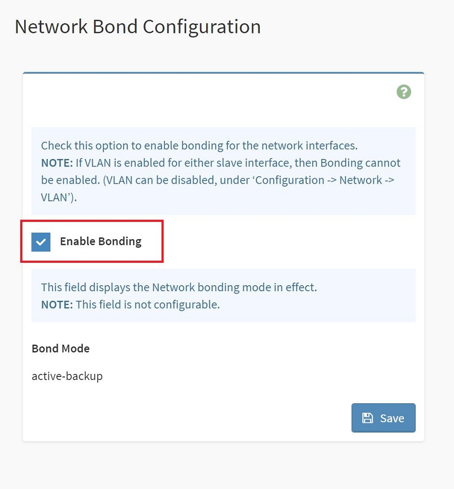
- To access bonding function in IPMI, go “Settings > Network Settings > Network Bond Configuration” and you shall see an “Enable Bonding” checkbox. And the bond mode is shown below as well. Tick the checkbox on your demand to configure bonding function, and click save.
 *Note that changing LAN settings will restart BMC network services. You will need to reconnect using new browser session after applying changes.
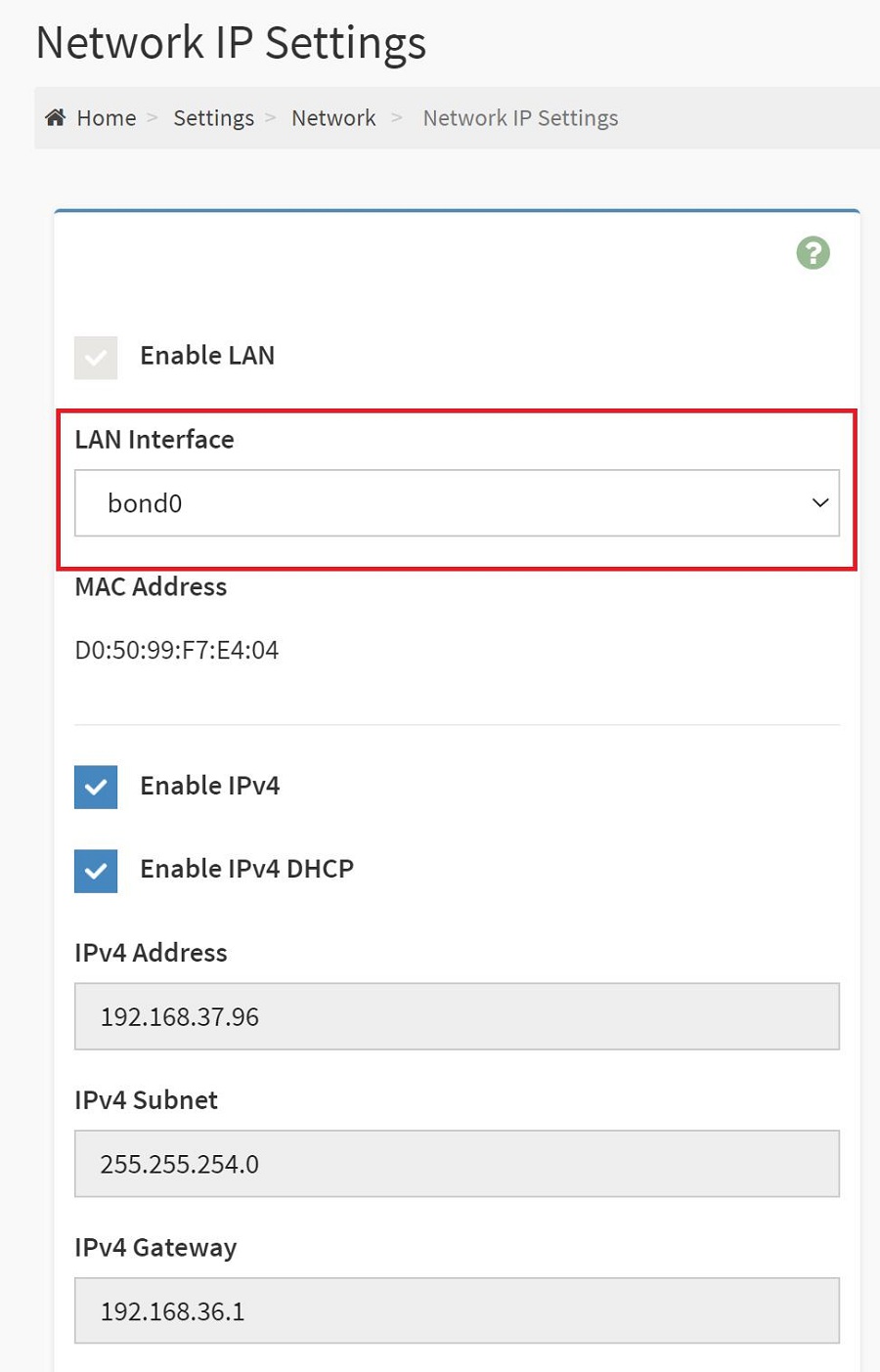
Bonding function check (with WebUI):
Bonding function could be checked with IPMI WebUI. If bonding is enabled, go “Settings > Network Settings > Network IP Settings”, you shall find the bond shown in LAN Interface.
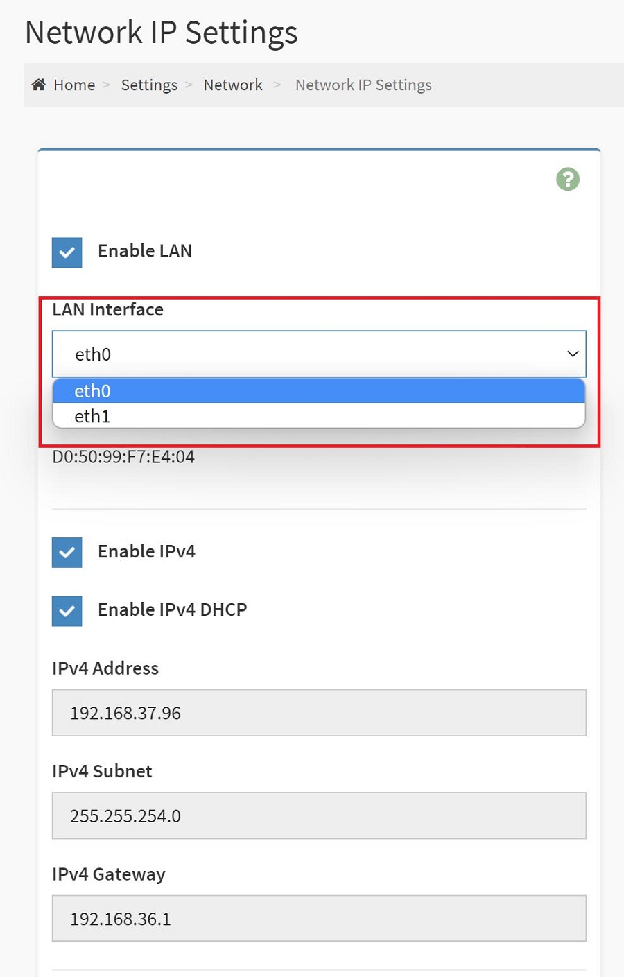
However, if the bond is disabled, you shall find the LAN inputs shown individually in LAN Interface.
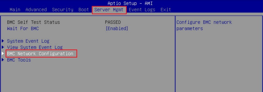
Bonding Function Check (in BIOS):
To check if the bonding function is working and configured successfully, we may check it out in BIOS menu > Server Mgmt > BMC Network Configuration.
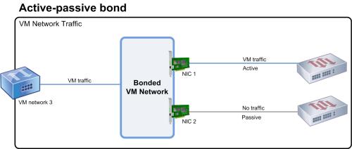
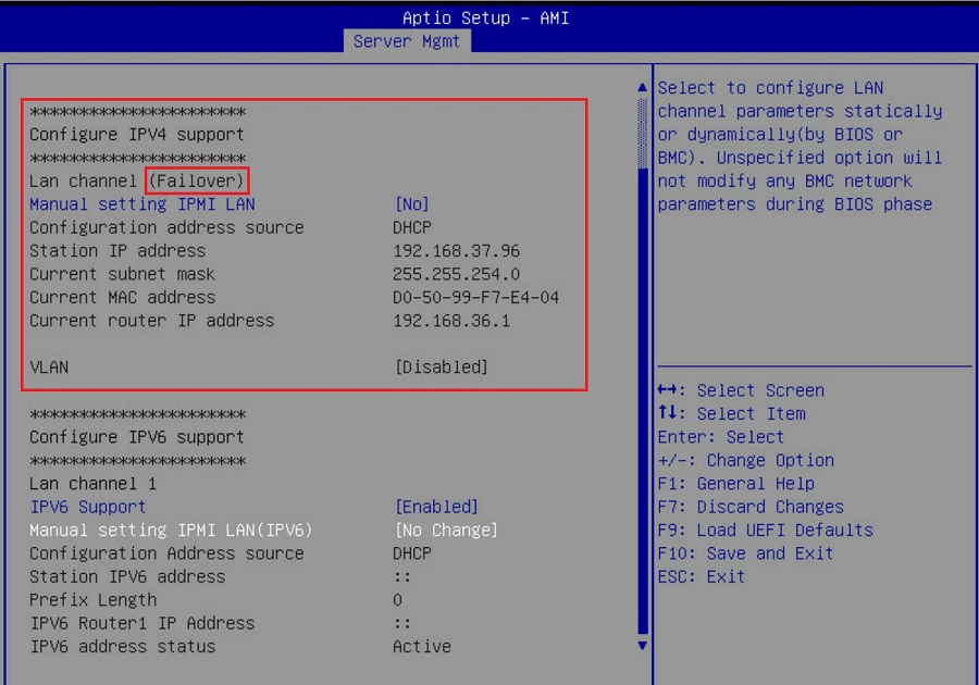
If bonding function is enabled, you shall find one and only one LAN signal detected with “(Failover)” written after the Lan channel.
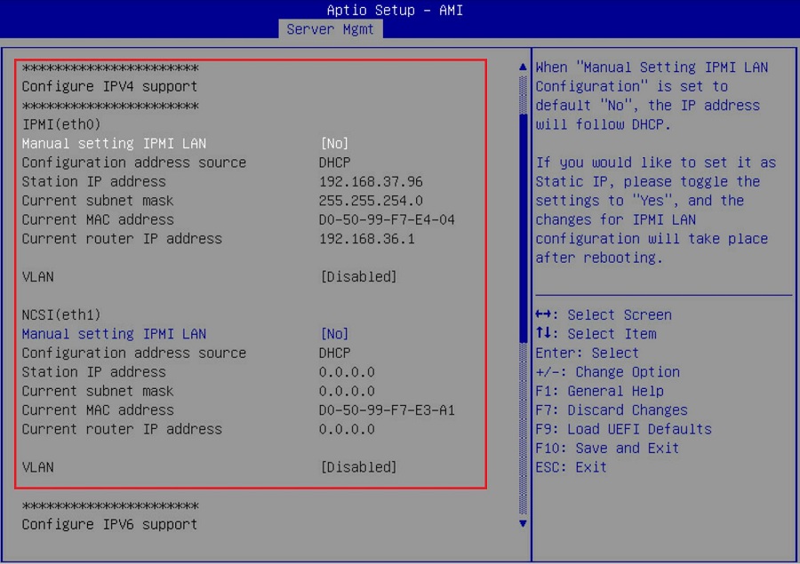
On the other hand, if the bonding function is disabled, you shall find Lan channels detected individually and listed below.
Done!
To enable/ disable network bonding using IPMI command, the following demonstration shows a way to install IPMI tool on a CentOS and configure with IPMI commands.
Preparation:
Access to the command line/ terminal window of a CentOS you have installed on the system you wish to configure network bonding.

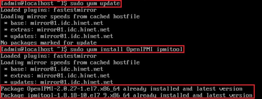
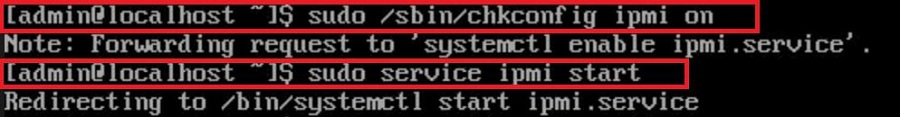
Input “sudo yum update” to update system repositories. Then, install IPMItool on a CentOS or RedHat system by running the command: “sudo yum install OpenIPMI ipmitool”. Wait for the installation to complete. The output should indicate that OpenIPMItool and IPMItool have been installed. You should see the version number of the software installed.
Once you have completed the installation, enable ipmitool access by running the command: “sudo /sbin/chkconfig ipmi on”. Then start the ipmitool service with the command: “sudo service ipmi start”.
Step:
- Now this OS is ready to configure local network bonding. Run:
“sudo ipmitool raw 0x32 0x71 0x1 0x0 0x0 0x1 0x64 0x0 0x3 0x1”
to DISABLE the IPMI bonding on default;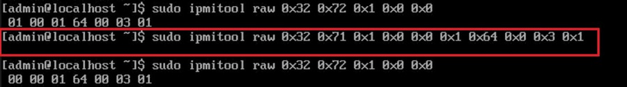
- To ENABLE bonding, it requires two command lines. First input:
“sudo ipmitool raw 0x32 0x71 6 0 3”, then
“sudo ipmitool raw 0x32 0x71 0x1 0x1 0x0 0x1 0x64 0x0 0x3 0x1”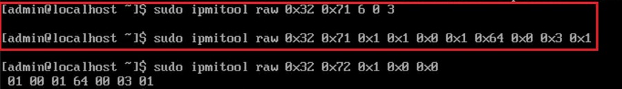
- To check if the bonding is enabled or not, run:
”sudo ipmitool raw 0x32 0x72 0x1 0x0 0x0”
If the output shows “00 00 01 64 00 03 01”, the bonding is disabled.
If it shows “01 00 01 64 00 03 01”, the bonding is enabled instead.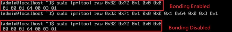
Remote IPMI command:
If you wish to remotely configure network bonding, install ipmitool on both the target system and the one you are running commands on.
The preparations and procedures are basically identical, except that you will have to add some information to the configuring command lines.
That is, for instance, Run:
“sudo ipmitool -I lanplus -H $target_ip -U $username -P $passwd raw 0x32 0x72 0x1 0x0 0x0”
Instead of
”sudo ipmitool raw 0x32 0x72 0x1 0x0 0x0” to check if bonding is enabled.
*Please be advised to fill in the right information on the above section labeled in red.
Done!
Issue

^ Using H5Viewer to remotely control Linux OS system in CMD mode. With Caps Lock pressed, only half of the letters are upper case.
In some Linux hosts, when the host is booted into text mode, CAPS LOCK LED status will not be updated properly. CAPS LOCK LED won’t turn ON/OFF while changing the CAPS lock status in the host OS.
In such cases, H5Viewer CAPS LOCK synchronization functionality will not work properly. The screen capture above shows an example of typing letters in H5Viewer (after pressing CAPS LOCK) will toggle between lower to upper case inside host.
Solution
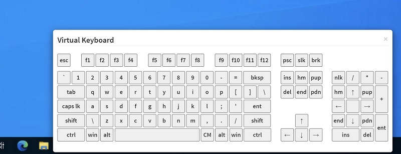
Currently due to the host side limitation of AMI, the issue could be bypassed with the Virtual keyboard function, or by pressing the Shift button to switch case.
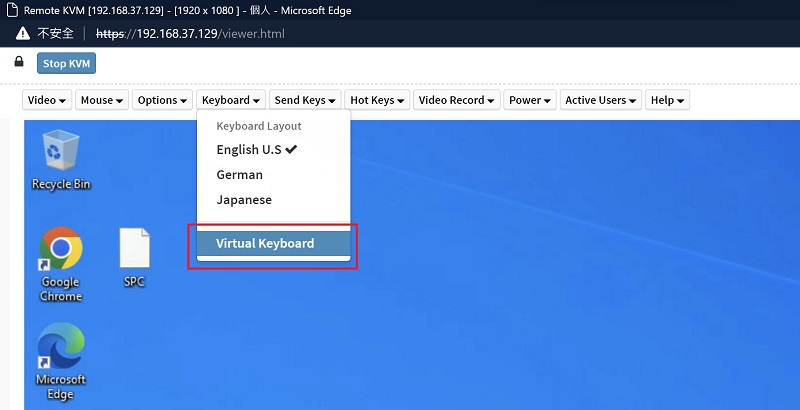
Or simply switch to JViewer to remotely control the system instead using H5Viewer.
Preparation:
1. For the BIOS method, it requires a more up to date motherboard and BIOS combination to include the “Load BMC Default Settings” item in BIOS Server Mgmt page.
2. For IPMI command, it requires a system with properly working BMC functions and IPMItool installed.
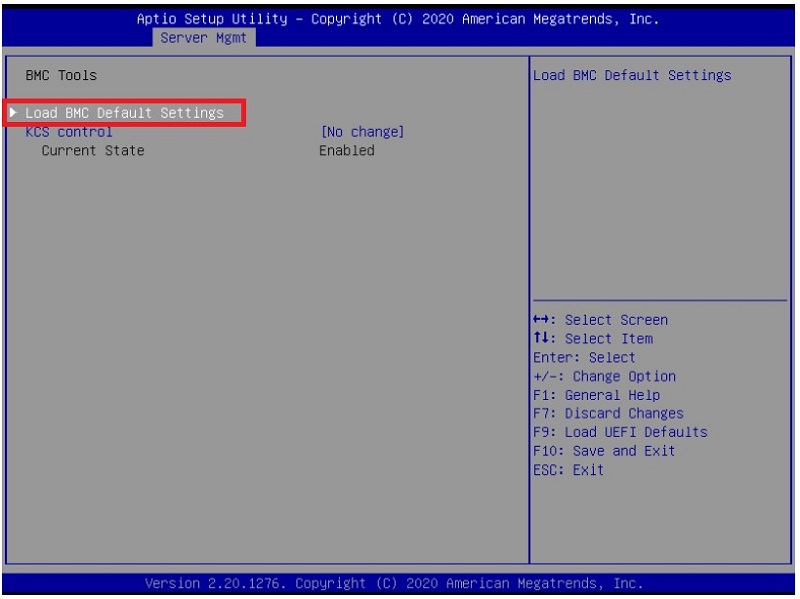
A. Load BMC Default settings via BIOS Configuration
1. Access BIOS page, select “Server Mgmt > BMC Tools”.
*Note that NOT all the motherboards/ BIOS versions include this function.
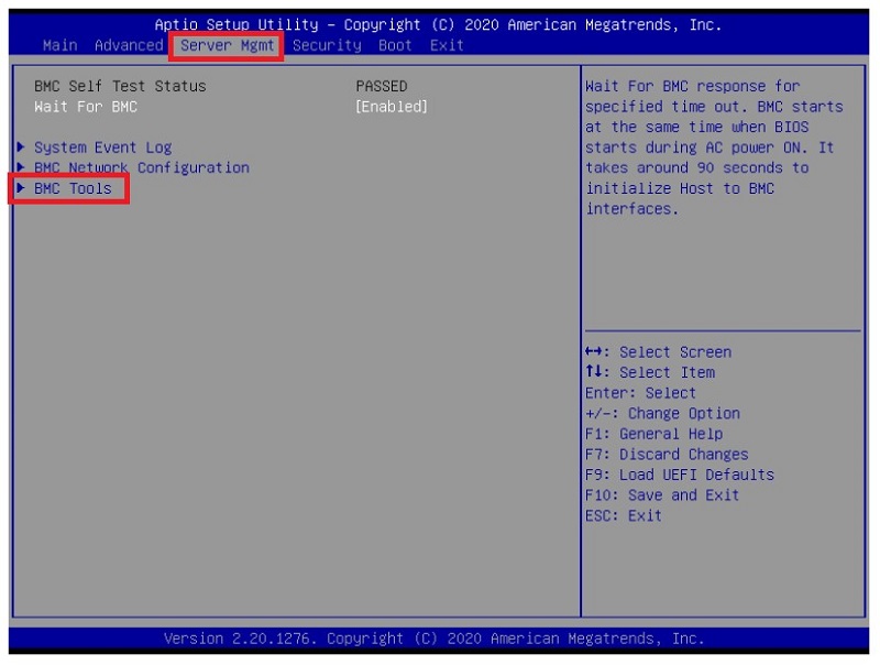
2. Select “Load BMC Default Settings” and confirm the upcoming questions, the procedure shall begin.
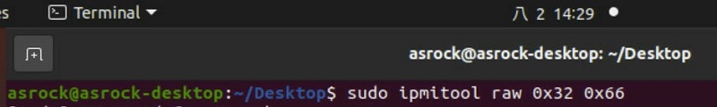
B. Load BMC Default Settings via IPMI Command
1. Open up an OS terminal, update system repositories and install IPMItool. Take Ubuntu for example, run “sudo apt update” and “sudo apt install ipmitool”.

2. Run “sudo ipmitool raw 0x32 0x66” to load BMC default settings.
3. Once the command is done, reboot the system to reset and complete the reset to the BMC.
C. Load BMC Default by updating to a new version/ same version again
It is rather intuitive to update to a whole new version of BMC or to the same version once again as loading to BMC default settings when the two methods mentioned above are unable to be performed.
Here is how: BMC Firmware Update by socflash
Done!
Before requesting for RMA, there are few methods to try and find out if your issue at hand is actually caused by our product itself:
1. If your system has issue booting up, please try below:
I. CMOS clearing: https://www.asrockrack.com/support/faq.asp?k=CMOS
II. Reseat all your hardware components and cables, make sure they are installed to the motherboard properly.
III. Remove all other hardware components until there is only one CPU and DIMM left, then try booting up again.
IV. If you have multiple systems or spare components at hand, you could try swapping some components which could be issue related with them.
V. If there is a later version of BIOS listed for your product on our site, please try updating to it and see if it fixes your issue.
How to update BIOS: ASRock Rack > Support
2. What information can you provide us to help:
I. Fill out your system configuration completely including firmware version (both BIOS and BMC) on our support site: https://event.asrockrack.com/tsd.asp?ln=en
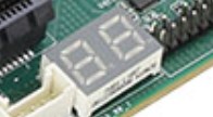
II. If there is a “Dr. Debug” on your motherboard, record the current code showing when the issue occurs.
Steps to update BIOS/BMC firmware via OpenBMC
Login page
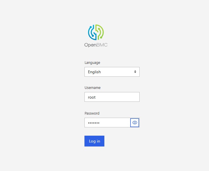
Default Username: root | Password: 0penBmc
BIOS/BMC Firmware Update
- [Operations] -> [Firmware]
This wizard will guide you through the firmware upgrade process.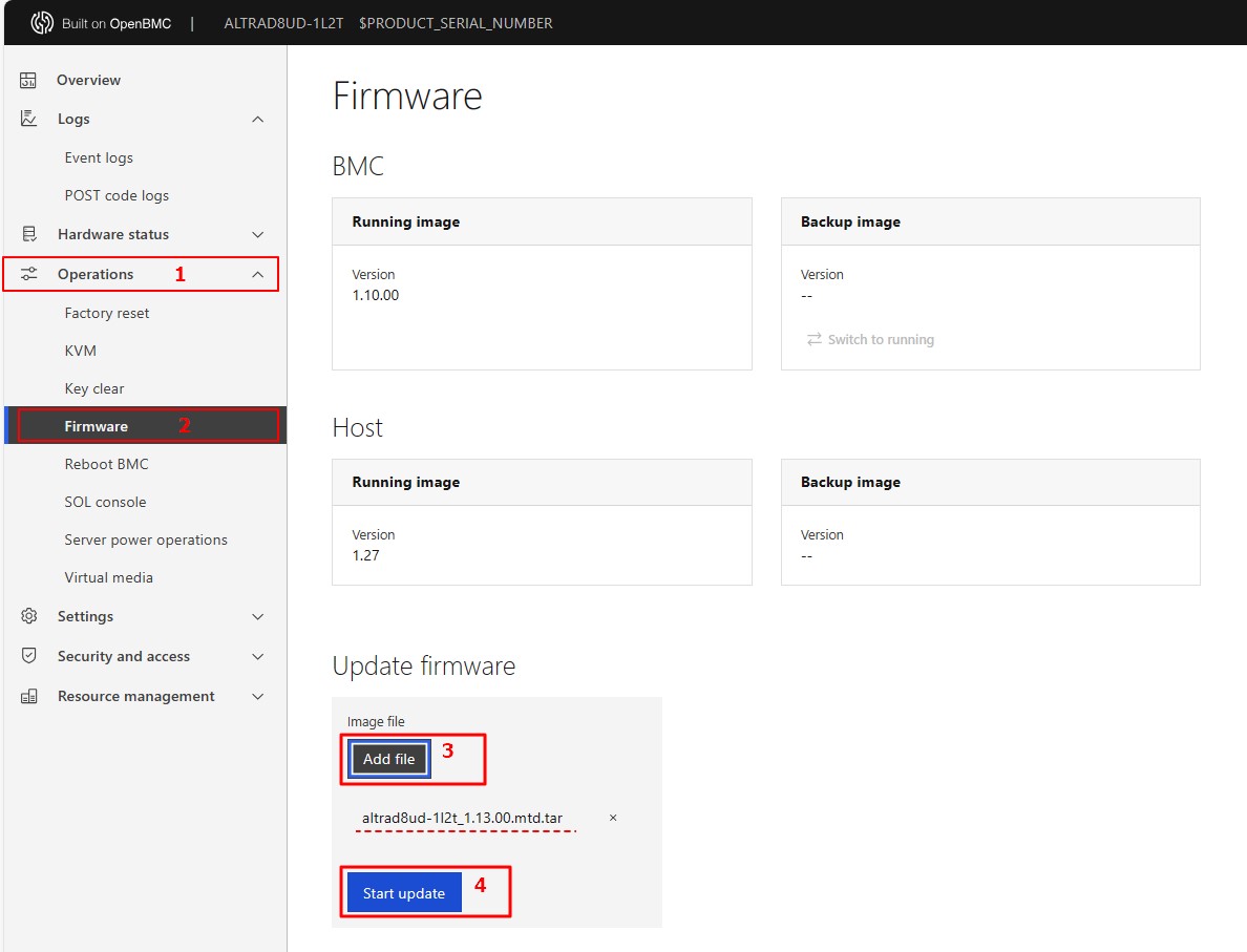
- Click “Add file” to select the BIOS/BMC FW file. Then click “Start update” for the upgrade process.
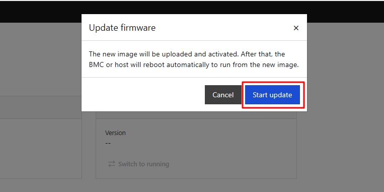
- Click “Start update” to continue the BIOS/BMC FW upgrade process.
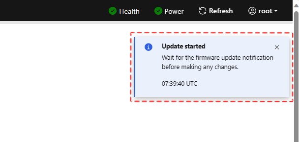
- The BIOS/BMC FW upgrade is being processed, please wait for a few minutes.
- BIOS/BMC FW upgrade is completed. Click "Refresh" and restart the system.
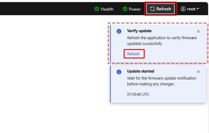
- Remark:
Clear the browser cookies after the BIOS/BMC FW upgrade is completed.
This guide features the cURL commands to update BIOS and BMC firmware for your server system which supports RedFish. Before we start, please make sure your host system has an IPMI or NC-SI LAN port connected to the internet and the BMC IP address of it for a client end in the same network segment to access.
1. BIOS Update:
curl -k -v -X POST https://[IP_address]/redfish/v1/UpdateService/upload --form 'UpdateFile=@[File_location]' --form 'UpdateParameters={"Targets":["/redfish/v1/UpdateService/FirmwareInventory/BIOS"]};type=application/json' --form 'OemParameters={"ImageType":"BIOS", "Config": 4, "Action": 3};type=application/json' -u [username]:[password] -H If-None-Match:W/\"1667287258\" -H "Expect:"
*We recommend this command which shuts down the host immediately and perform BIOS update.
For BIOS update, here are the definitions to the available values for "config" and "action":
'OemParameters={"ImageType":"BIOS", “Config”: config, “Action”: action}’
config
2: Preserve BIOS settings
4: Overwrite BIOS settings
action
1: Update on host shutdown
2: Update immediately without changing host state
3: Shutdown host to update
If the update request is successfully sent off, the system would return an Accepted message with a 2xx code: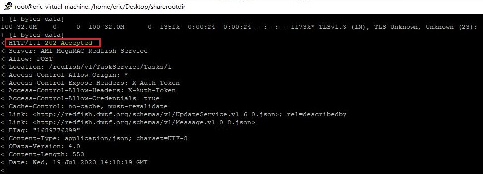
You may also check the update progress by visiting:
https://[host_IP_addr]/redfish/v1/UpdateService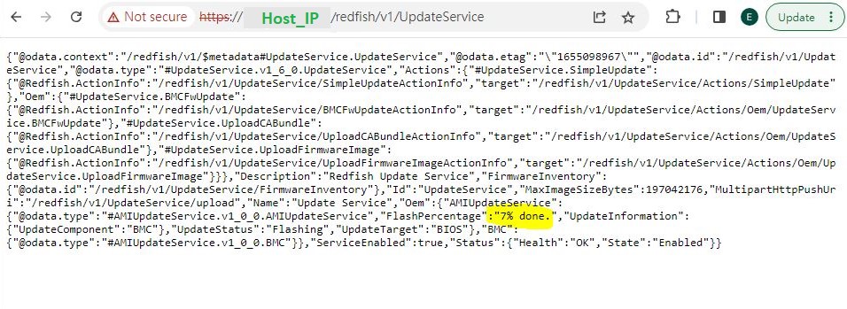
2. BMC Update:
curl -k -v -X POST https://[IP_address]/redfish/v1/UpdateService/upload --form 'UpdateFile=@[File_location] ' --form 'UpdateParameters={"Targets":["/redfish/v1/UpdateService/FirmwareInventory/BMC"]};type=application/json' --form 'OemParameters={"ImageType":"BMC"};type=application/json' -u [username]:[password] -H If-None-Match:W/\"1667287258\" -H "Expect:"
If the update request is successfully sent off, the system would return an Accepted message with a 2xx code as well.
3. Reboot Host:
In case you are not using a shutdown action parameter (3) for the BIOS update command, or to view the latest firmware information of your current host after the update, please reboot your host with the following command:
curl -k -v -X POST https://[BMC_IP]/redfish/v1/Systems/Self/Actions/ComputerSystem.Reset -d '{"ResetType" : "GracefulRestart"} -H "Content-Type: application/json" -H "X-Auth-Token: [token]"
4. Troubleshooting:
If an issue occurs during the update (e.g. the procedure did not start, or an error code "Status:500 Internal Server Error" occurred), you can try below methods such as the power actions or resetting BMC to default according to the scenarios:
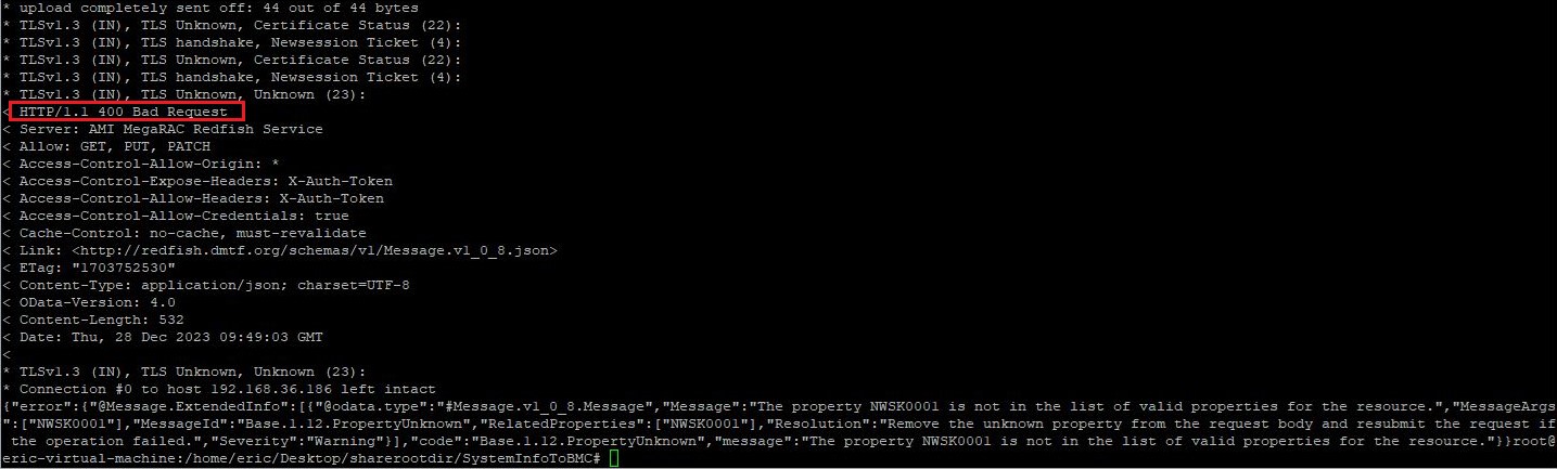
i. Double checking your command:
If your cURL request was returned by an error code 400, it means that the request command was incorrect. In other words, the request sent by the client to the host server did NOT follow the rules. The client should modify the request command before retrying so that it could be understood by the host.
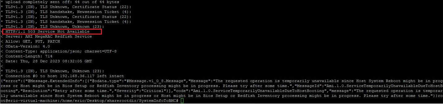
ii. Reboot Host:
If the expected update procedure does not start up, you may try powering off your system, or try rebooting it:
curl -k -v -X POST https://[BMC_IP]/redfish/v1/Systems/Self/Actions/ComputerSystem.Reset -d '{"ResetType" : "GracefulRestart"} -H "Content-Type: application/json" -H "X-Auth-Token: [token]"
ResetType Allowable values :
“On” for Host power on
“GracefulRestart” for Host reboot
“GracefulShutdown” for Host soft power off
“ForceOff” for Host hard power off
iii. BMC set to default:
If you encountered an error code 500 issue, this could be related to corrupted RedFish data. The overall solution is to resend a brand new copy of RedFish data to the server again. To do so, we flash BMC to the same version with items other than RedFish preserved, or simply update your BMC.
To preserve your current BMC config:
curl -k -v -X PATCH https:// [BMC_IP]/redfish/v1/UpdateService -d '{"Oem": {"AMIUpdateService": {"PreserveConfiguration": {"Authentication": true,"FRU": true,"IPMI": true,"KVM": true,"NTP": true,"Network": true,"REDFISH": false,"SDR": true,"SEL": true,"SNMP": true,"SSH": true,"Syslog": true,"WEB": true} } } }' -u [username]:[password] -H If-None-Match:W/\"1667287258\" -H "Expect:" -H "Content-Type: application/json"
5. Report an issue to us:
If there is an issue that cannot be resolved or further assistance is required, please visit https://event.asrockrack.com/tsd.asp and fill out the form as detailed as possible so we could provide an efficient tech support.
Preparation
The following guide will help you through enabling dual screen with your Ubuntu OS on your ASRock Rack product. This example would be based on the scenario of enabling dual-screen on a B650D4U system with Ubuntu 22.04.4. Before this procedure, the system is only capable of displaying video through the onboard VGA port but not the HDMI port simultaneously.
For detail and further resource, please refer to:
Radeon™ Software for Linux® Installation — amdgpu graphics and compute stack unknown-build documentation (amdgpu-install.readthedocs.io)
Steps
1. First, we install the AMDGPU driver: 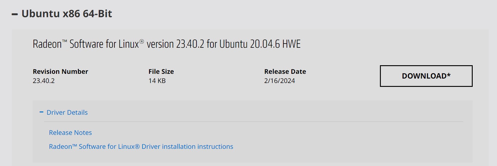
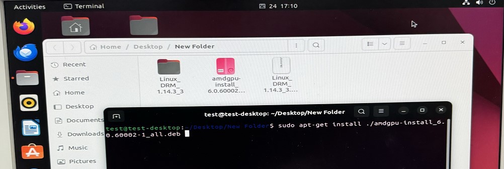
After that, run “sudo amdgpu-install -y --accept-eula” to finish installation: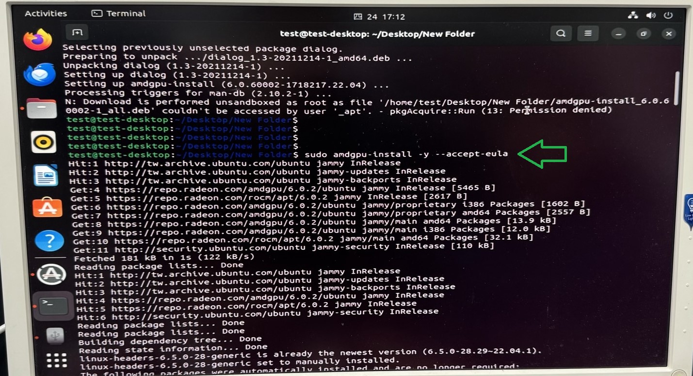
2. Then, proceed to install the ASPEED Graphics Driver:ASPEED - Drivers Download (aspeedtech.com)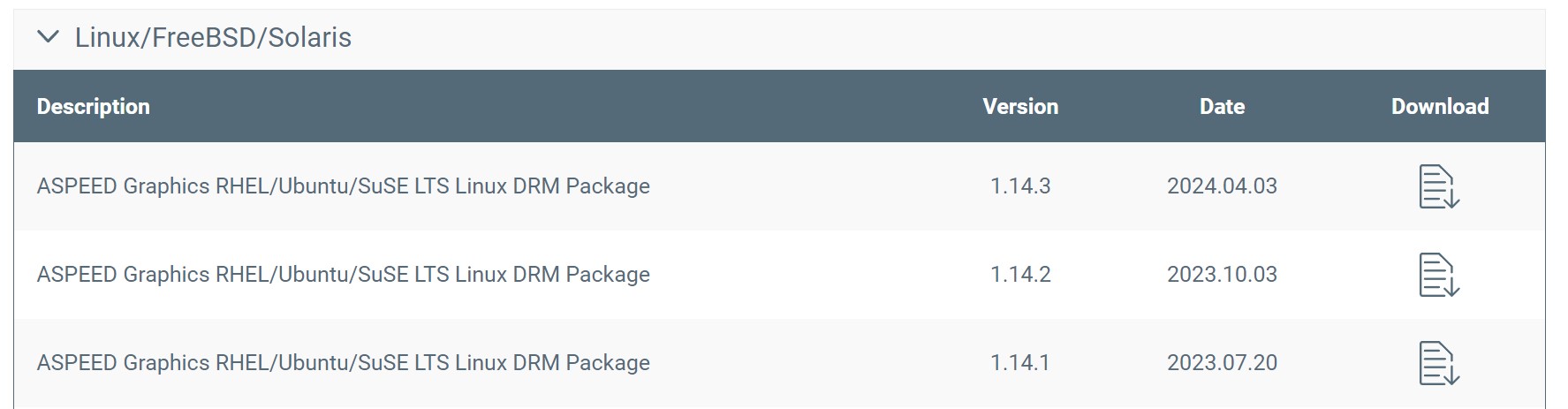
Download the package and direct into the DKMS folder. Then run “sudo dpkg -i ast-drm-linux6.2.deb” to install the latest Linux package.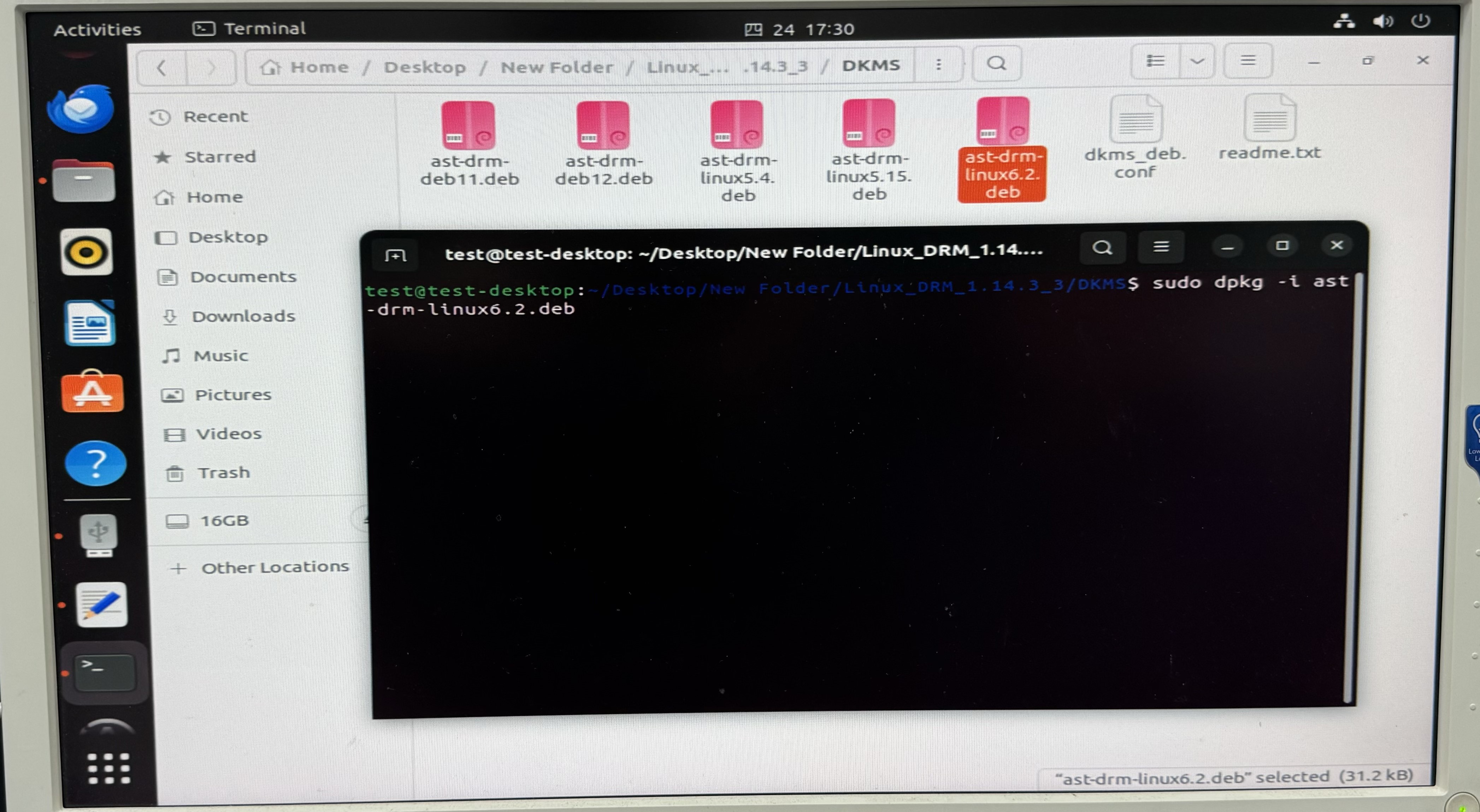
Completion: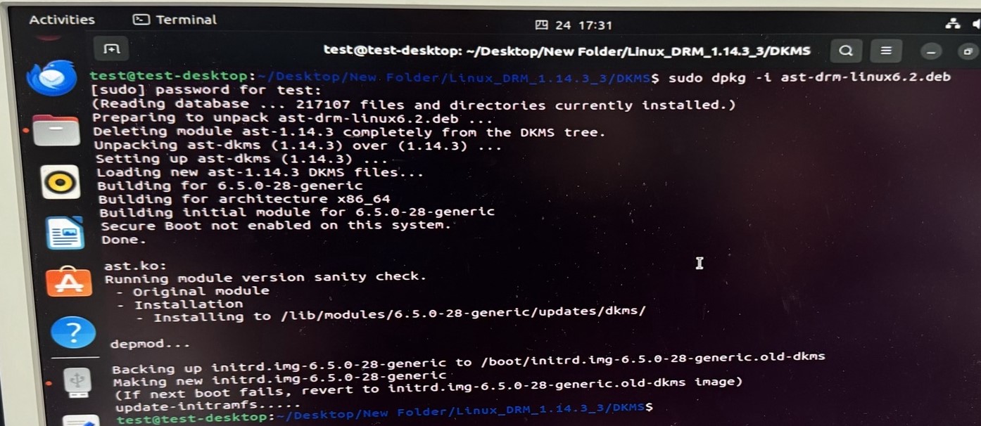
3. Finally, install LightDM display manager by running “sudo apt install lightdm”, and choose lightdm as your Default display manager: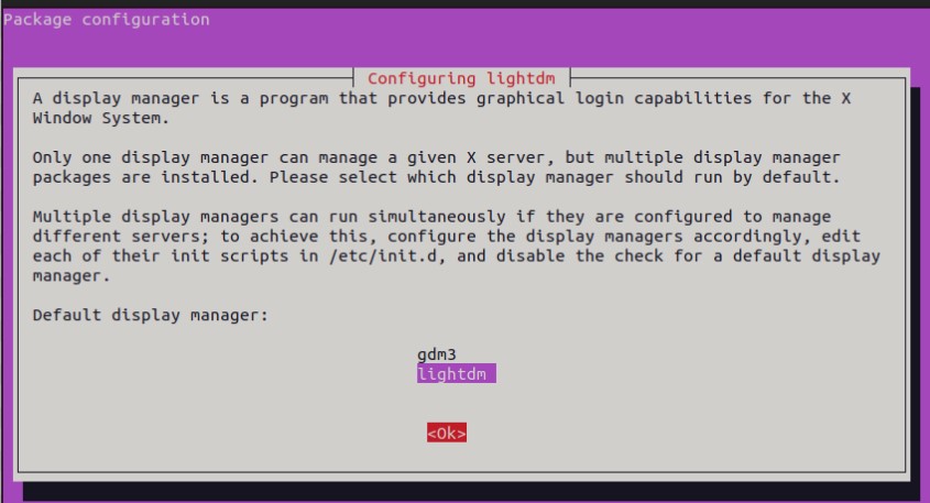
4. Reboot the system, and click on the Ubuntu LOGO and choose “Ubuntu on Wayland”.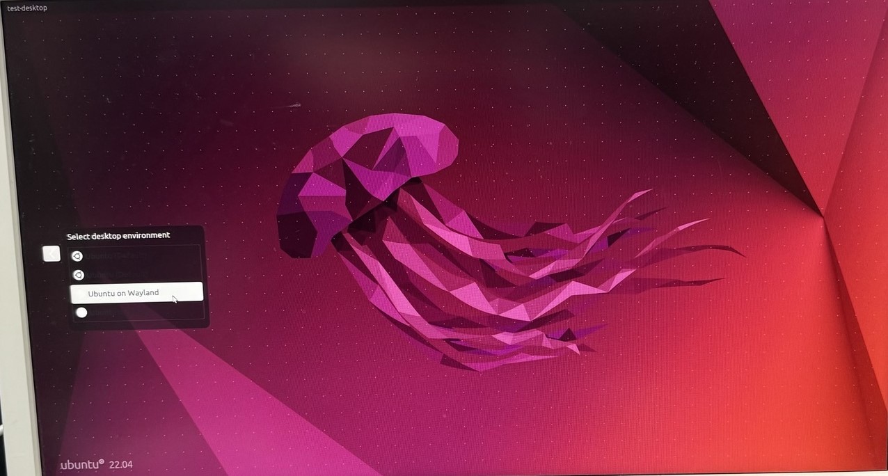
5. Upon login, you will notice that both the onboard VGA and the HDMI are now displaying video. Be advised that the HDMI output is restricted to only be used as a secondary monitor with the VGA output being the primary one.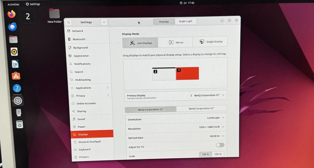
Preparation
1. Make sure your Altra motherboard / system to adjust fan speed on has a well-functioning BMC, so it can later be configured with ipmitool commands.
2. All fans are properly powered and seated to the motherboard / system so there would not be any unexpected errors.
Also make sure that the fans do have 4-pin or more to support manual speed configuration.
Steps
1. Open up a Linux terminal, update system repositories and install ipmitool. Take Ubuntu for example, run “sudo apt update” and “sudo apt install ipmitool”.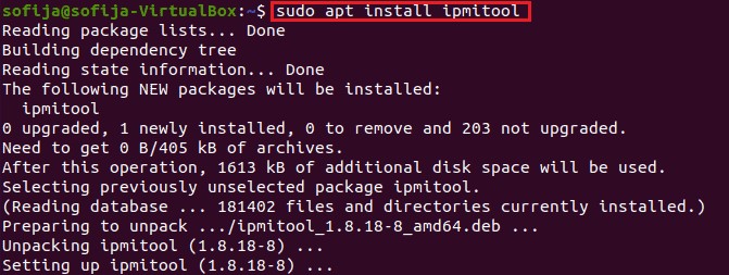
2. All the fans are set to act correspondingly to the CPU temperature by default. To manually configure them, here are some sample commands to apply your designated fan speed:
a. All fans run at full speed:
>> sudo ipmitool raw 0x3a 0x1 0x64 0x64 0x64 0x64 0x64 0x64 0x64 0x64
b. All fans run at half speed:
>> sudo ipmitool raw 0x3a 0x1 0x32 0x32 0x32 0x32 0x32 0x32 0x32 0x32
c. All fans set to default mode (operate based on CPU temperature):
>> sudo ipmitool raw 0x3a 0x1 0x0 0x0 0x0 0x0 0x0 0x0 0x0 0x0
*To set fan speed to a specific value, simply change the 0x64 or 0x32’s above to 0xHexValue. As 64 in hex equals to 100 in decimal, 32 in hex equals to 50. Similarly, apply the hex value of any % fan duty on your demand.
e.g. Use 0x50 for the fans to work at 80% speed.
3. To check if the fans are working correctly at the designated speed, check out the OpenBMC WebUI > Hardware status > Sensors, all the fans should be listed with their key information such as Current Speed value, Upper and Lower critical value, etc.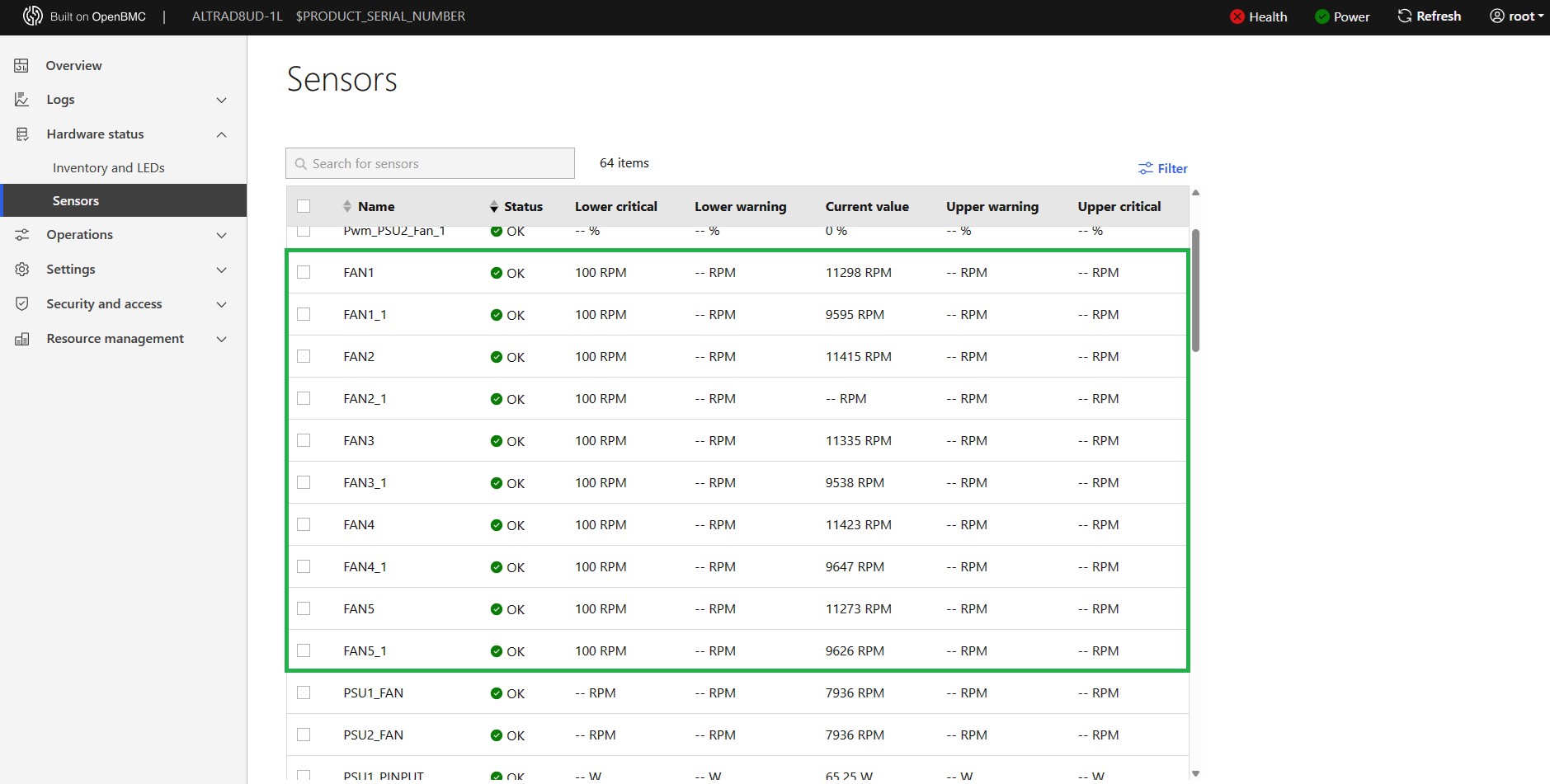
Here is an easy method to monitor the boot procedure for our ALTRA series motherboard and systems. Simply follow below steps to access the host system via SSH session remotely:
1. Run the ssh command below with the Host system IP at your command prompt on a client system to start an SSH session:
ssh root@<Host_BMC_IP> -p 2200
2. First time running the command, you may receive a return message which requires you to grant access. Simply enter “yes” to proceed.
3. Then enter your BMC password, the default password would be “0penBmc”.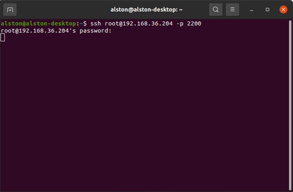
4. After that, power on or reboot the host. Soon, you shall see the boot process begins updating rapidly in the window above.

Issue:
On ARM-based motherboards (ALTRA, AMPONE series), when the system is running some specific OS such as RHEL 9.5 and 9.6, executing the “Orderly Shutdown” or “Orderly Reboot” function from WebUI may cause the system to enter and remain on a black screen.
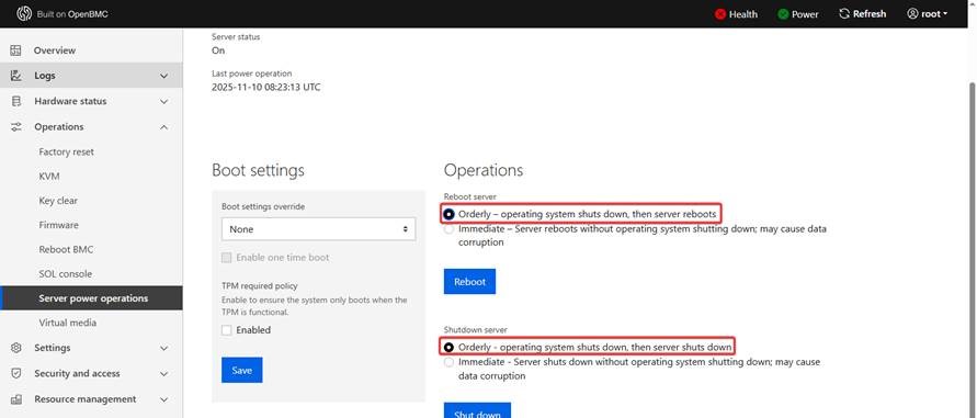
Step to resolve the issue:
1. Perform an AC power cycle, then boot into the OS
2. Open a terminal and execute the following commands to install the “acpid” module.
A. $ dnf install acpid
B. $ systemctl enable acpid
C. $ systemctl start acpid
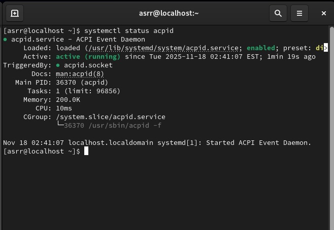
3. After installation, run the following command to verify whether the “acpid” module is functioning properly, as shown in the image below.
$ systemctl status acpid #check acpid status
4. Try the functions from the WebUI again to check whether the issue has been resolved.
Description:
When installing windows iso with multiple language, sometimes mouse or keyboard has no response. This is caused by the confliction when iKVM try to mount different region input method. And this can be prevented by inject ASPEED driver into windows iso first
1. Download and install Windows ADK for Windows Server 2025
https://learn.microsoft.com/en-us/windows-hardware/get-started/adk-install#download-the-adk-101280001-november-2025
2. Create a folder for making iso with ASPEED driver later Ex: mkdir H:\WS2025_mod
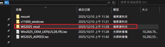
3. Mount your original windows server 2025 iso on computer Ex: mount as I:\
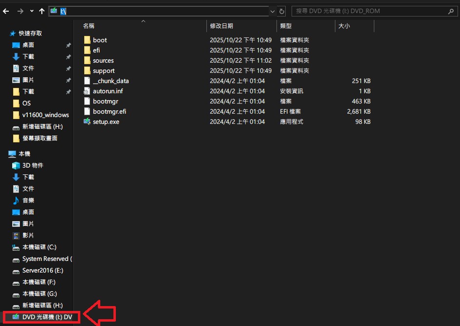
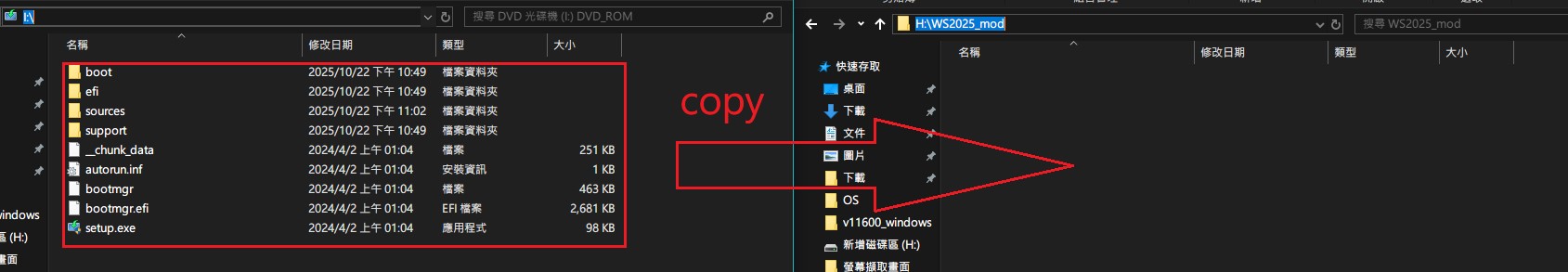
4. Copy all the contents in windows server 2025 iso to temp folder
Ex: Copy all the contents from D:\ to H:\WS2025_mod
5. Check if there is install.wim in C:\WS2025_mod\sources\
P.S if you only find install.esd, then please execute following CMD to transfer install.esd to install.wim
=> dism /mount-wim /wimfile:H:\WS2025_mod\sources\install.wim /index:1 /mountdir:H:\mount

6. Mkdir H:\mount
7. Mount install.wim
=> dism /mount-wim /wimfile:H:\WS2025_mod\sources\install.wim /index:1 /mountdir:H:\mount
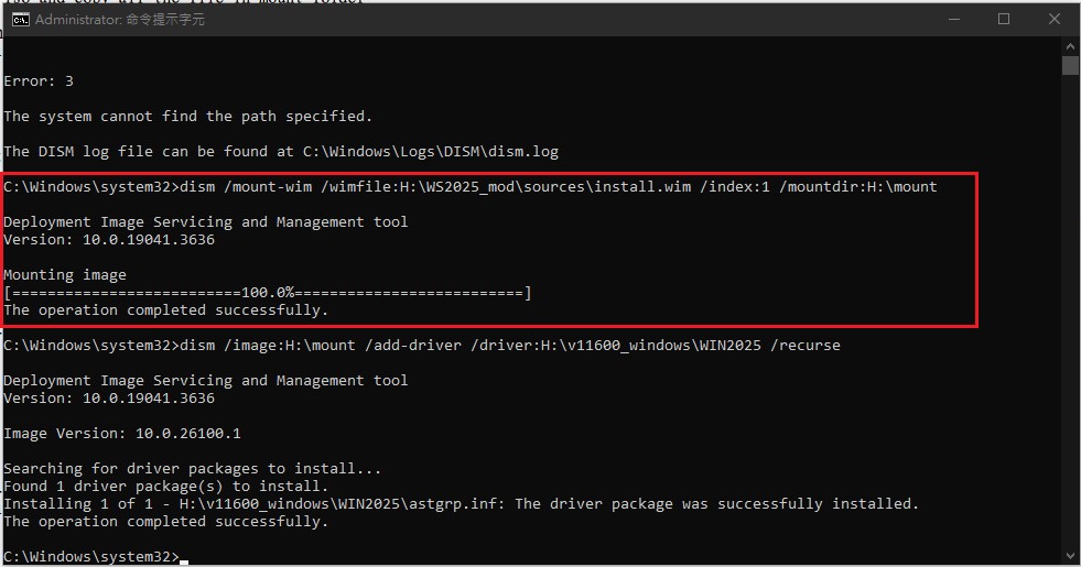
8. Inject ASPEED Driver
Ex: assume your ASPEED driver is at H:\v11600_windows\WIN2025
then please execute CMD
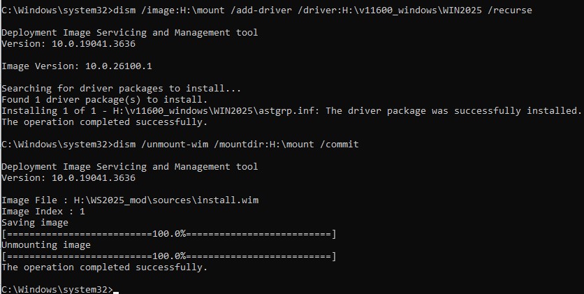
=> dism /image:H:\mount /add-driver /driver:H:\v11600_windows\WIN2025 /recurse

9. umount the temp folder => dism /unmount-wim /mountdir:H:\mount /commit
10. Execute oscdimg in Windows ADK for Windows Server 2025
Ex:
> Open terminal
> cd to C:\Program Files (x86)\Windows Kits\10\Assessment and Deployment Kit\Deployment Tools\amd64\Oscdimg\oscdimg.exe (normally, oscdimg should at this location)
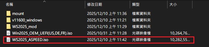
> execute: oscdimg -m -o -u2 -udfver102 H:\WS2025_mod H:\WS2025_ASPEED.iso
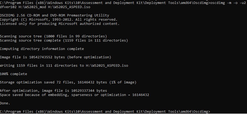
11. new iso should at C:\WS2025_ASPEED.iso
The option name varies across different platforms. Please refer to the following screenshots to identify the correct option and its location in the BIOS menu.
Intel platform
● W680 / Z690 series
[BIOS SETUP] – [Advanced] – [Chipset Configuration]

● W880 / Z890 / W790 seriess
[BIOS SETUP] – [Advanced] – [Chipset Configuration]

Note:
- Please first update BIOS to the latest version to obtain the option on the above platforms.
- Users can enable the option if encounter security related problems.